Overview
The ANT BMS 17S-24S Smart Battery Protection Board (BMS) is designed for 17S to 24S LiFePO4, Li-ion, and LTO battery packs. It includes built-in Bluetooth for Android/iOS monitoring and supports the same-port wiring method for charge/discharge.
Key Features
- Battery strings: 17S to 24S
- Built-in Bluetooth; supports Android / iOS phone monitoring
- Passive balancing: 100 mA
- Short circuit protection: supported
- Supports single-cell voltage dropout detection
- Power supply mode: battery pack self-powered and 20-80V DC input
- Temperature sensing supported (T1 / T2)
Specifications
| Number of battery strings | 17S to 24S |
| Current versions | 125A / 250A / 325A / 425A / 550A; 850A peak current (as stated) |
| Power supply mode | The battery pack is self-powered and 20-80V DC input |
| Single cell voltage detection range | 0-5V |
| Single cell voltage detection error | <20 mV over full operating range; typical error value <10 mV |
| Single-cell voltage dropout detection | Supported |
| Balance current | 100 mA (passive balance) |
| Wiring method | Same port |
| Short circuit protection | Support |
| Bluetooth | Bluetooth built-in; support for Android / iOS phone |
| Temperature detection | -40 to 125°C |
| Total voltage detection range | 0-100V |
| Total voltage detection accuracy | <0.5% FSR (FSR = full scale) |
| Current sense shunt | -150A to 300A; error <0.5% FSR |
| SoC estimation accuracy | Error <8% (operating conditions) |
| Battery remaining capacity accuracy | Error range is less than 8% |
| Total Cycle AH cumulative value | Half of the charge/discharge value |
| Operating power consumption | <5 mA (without communication) / 15 mA (485/CAN) |
| Standby power consumption | <2 mA |
| Operating temperature | -40 to 85°C |
| Storing temperature | -40 to 95°C |
| Dimensions (as marked) | 9 cm (top width); 16.1 cm (height); 7.3 cm (bottom width); 11.1 cm (right-side marked dimension) |
| Cable length (as marked) | 15 cm |
Wiring & Activation Notes
Main connection notes
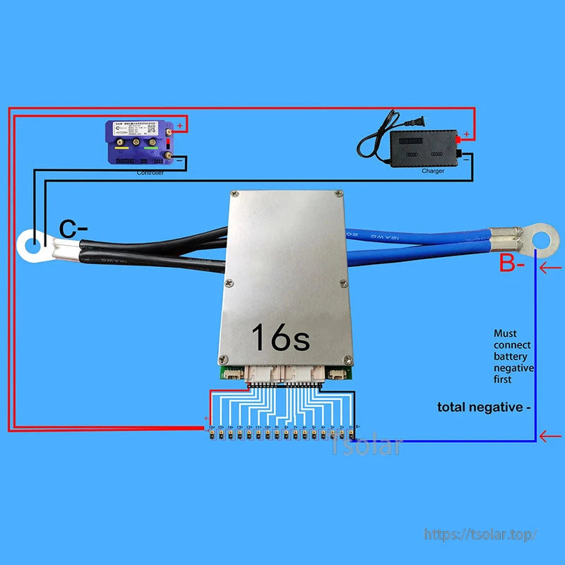
- Connect the B-terminal to the main negative electrode of the battery first.
- The negative pole of the charger and the negative pole of the load are connected to the C-terminal of the protective plate.
- Use a multimeter to measure the voltage of each string on the cable ports and confirm it is correct before inserting it into the protection board.
Balance cable sequence notes (provided guidance)
- The first black wire on the far right connects to the total negative electrode of the battery pack (negative electrode of the first cell).
- Starting from the black wire, connect the first white wire from right to left to the positive electrode of the first cell, then the second cell, third cell, and so on, connecting to the positive electrode of each cell in sequence.
- The minimum number of cells to be connected is 8S. Batteries of less than 32S are not left empty.
- After connecting, use a multimeter to measure the voltage on the plug row, and confirm the voltage is correct before plugging into the protection board.
- Note: the last red wire on the third (last) socket is B+, which supplies power to the protection board. It connects to the cable of the last cell of the battery pack; two wires need to be connected on the last positive pole of the battery to the BMS. There is a hole behind the last red wire of the third socket and B+ is redundant and can be left unused.
BMS activation (provided guidance)
- Must connect blue silicone wire B- to battery total negative.
- Connect balance cable; must connect as the diagram shows.
- Before connecting to BMS, use a voltage meter to measure each series voltage; start from battery negative when measuring.
- After all wires are connected correctly, connect the red and black wire of the 4P socket to 3-5V; BMS can be activated after 1-2 seconds.
- There will be a “DI” sound and both ends will have red light flashing after activation.
- Additional note: connect the power cord to a voltage of 3-5 volts to activate the power; alternatively, if the output voltage of the charger is higher than the current voltage of the battery pack by more than 2V, it can be charged and activated for startup.
Applications
- 17S-24S LiFePO4 / Li-ion / LTO battery pack protection and monitoring
- Battery systems requiring Bluetooth status monitoring and passive balancing
For the latest app access and product documentation, contact customer support at https://tsolar.top/ or email service@tsolar.top.
Note: Carefully check the version needed before placing an order.
Details
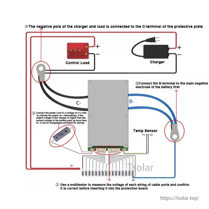
Same-port wiring keeps charge and discharge on the C- terminal, with B- connected to the battery pack negative first and T1/T2 available for temperature sensing.
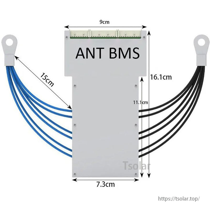
A compact 16.1 cm tall enclosure with 15 cm leads helps with fit checks and cable routing inside the battery pack.