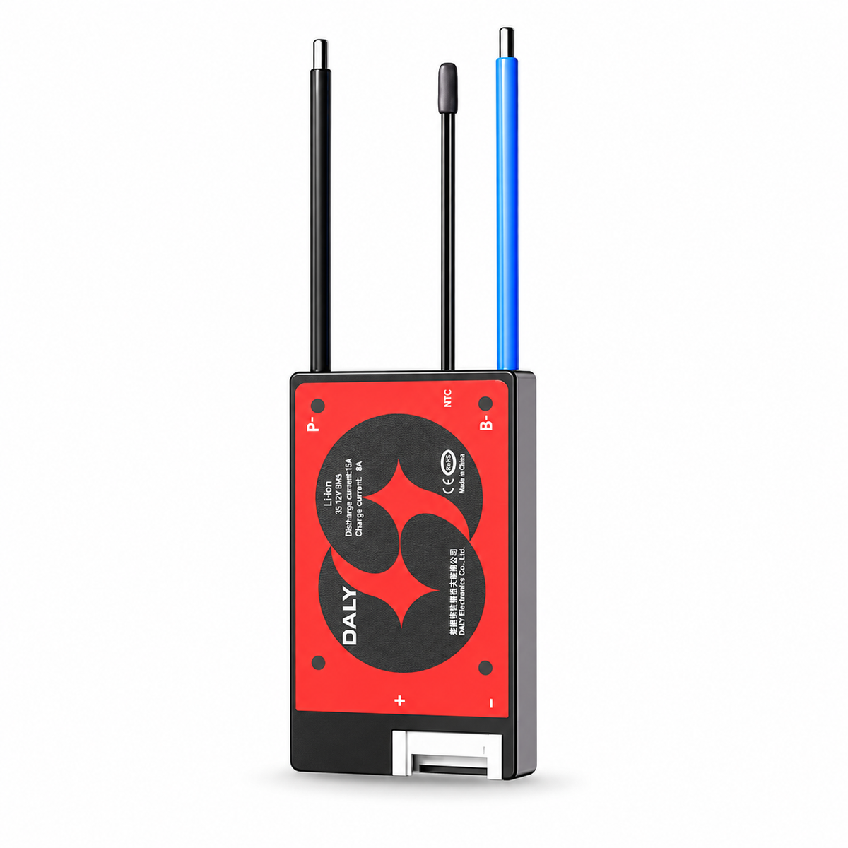
DALY Hardware BMS with Passive Balancing and Temperature Protection
Protect a compatible lithium battery pack with the DALY compact red-board battery management system. Choose the exact battery chemistry, series count and current rating. This is a fixed-configuration hardware BMS with a common charge/discharge port, passive cell balancing and NTC temperature protection. All variants in this listing are supplied without Bluetooth; app monitoring and communication accessories are not included.
Available Battery Configurations
Li-ion / NCM: 3S 12V, 7S 24V, 10S 36V, 13S 48V, 14S 48V, 16S 60V, 17S 60V and 20S 72V. LiFePO4: 4S 12V, 8S 24V, 12S 36V, 15S 48V, 16S 48V, 20S 60V and 24S 72V. Voltage labels follow the supplier's pack-voltage naming and are not charger output voltages. 15A and 20A are offered only for Li-ion 3S/7S/10S/13S and LiFePO4 4S/8S/12S. 40A, 60A, 100A, 150A and 200A are offered across the listed battery configurations. Only the 89 actual in-stock supplier combinations are offered.
Match both chemistry and series count to your pack. These are not adjustable universal-range boards. Supplier charger references are 4.2V × cell count for Li-ion and 3.65V × cell count for LiFePO4. Select a suitable charger for the actual cells.
Construction and Features
- Supplier describes encapsulated construction for resistance to splashes, vibration and oxidation; patent reference ZL201821243978.5. No IP rating is supplied.
- Passive balancing, overcharge, overdischarge, charge/discharge overcurrent, short-circuit and temperature protection.
- Supplier working consumption reference below 400µA and main-circuit conduction resistance below 20mΩ.
- Low-resistance MOS components and heat-spreading housing. Thick-copper PCB is specifically illustrated for M-series 150A/200A.
- NTC temperature protection; H-series uses integrated NTC according to the package illustration.
Series, Dimensions and Leads — Supplier Reference
| Family | Current ratings | Hardware series range reference | Dimensions | B-/P- leads |
|---|---|---|---|---|
| G | 15A / 20A | 3–13S | 34 × 59 × 9mm | 15A: 16AWG / 100mm; 20A: 14AWG / 100mm |
| H | 40A / 60A | 3–16S | 48 × 75 × 14mm | 10AWG / 160mm |
| K | 40A / 60A / 100A | 3–24S | 65 × 123 × 14mm | 40/60A: 10AWG / 100mm; 100A: 7AWG / 100mm |
| M | 150A / 200A | 3–24S | 66 × 164 × 21mm | 4AWG / 150mm |
Sense leads are 24AWG; actual length depends on the supplied configuration. Series ranges above describe product families, not a user-selectable range of an individual board. The listing does not identify H versus K for every 40/60A SKU; confirm the actual board label and footprint. Gallery is representative and is not assigned to individual variants.
Specific 7S Li-ion G-Series Reference Sheets
| Parameter | 15A | 20A |
|---|---|---|
| Board model | J13G (3–13S family) | |
| Discharge current | 15A | 20A |
| Discharge overcurrent threshold | 50 ± 10A | 60 ± 10A |
| Charging current | 8A | 10A |
| Charge overcurrent threshold | 10 ± 2A | 13 ± 3A |
| Cell overcharge threshold | 4.25 ± 0.05V | |
| Cell overdischarge threshold | 2.7 ± 0.05V | |
| 7S charger voltage | 29.4V | |
| Output leads | 16AWG / 110mm | 14AWG / 130mm |
| Sense harness | 24AWG / 350mm | |
| Dimensions / weight | 59 × 34 × 9mm / 42 ± 5g | |
These two sheets specifically illustrate 7S Li-ion. Their charging currents, charge-overcurrent thresholds and output lead lengths differ from the general family table. Do not apply the 29.4V charger value or these chemistry thresholds to other series or LiFePO4 packs. Verify the delivered configuration before installation.
General Current Protection Reference
| Family / rating | Charge current | Charge overcurrent | Discharge current | Discharge overcurrent |
|---|---|---|---|---|
| G 15A | 15A | 20 ± 3A | 15A | 50 ± 10A |
| G 20A | 20A | 25 ± 3A | 20A | 60 ± 10A |
| H 40A | 40A | 56 ± 10A | 40A | 138 ± 30A |
| H 60A | 60A | 70 ± 10A | 60A | 180 ± 30A |
| K 40A | 40A | 50 ± 10A | 40A | 125 ± 10A |
| K 60A | 60A | 70 ± 10A | 60A | 175 ± 10A |
| K 100A | 100A | 106 ± 20A | 100A | 256 ± 20A |
| M 150A | 150A | 400 ± 30A | 150A | 300 ± 20A |
| M 200A | 200A | 400 ± 30A | 200A | 400 ± 30A |
Supplier general laboratory reference; do not use overcurrent trip thresholds as continuous operating ratings. G-series charging figures conflict with the specific 7S sheets above. Current capacity depends on the actual hardware, temperature, wiring and installation.
Balancing and Protection Settings — General Reference
| Balancing start voltage | Li-ion 4.075–4.175V; LiFePO4 3.475–3.525V per cell |
|---|---|
| Balancing condition | Cell voltage reaches the configured balancing start voltage |
| Balancing current | Li-ion 75 ± 25mA / 100 ± 25mA depending on version; LiFePO4 70 ± 25mA |
| Cell overcharge protection | Li-ion 4.25 ± 0.05V; LiFePO4 3.65 ± 0.05V |
| Overcharge delay | 1 ± 0.5s |
| Overcharge recovery | Li-ion 4.15 ± 0.05V / 4.10 ± 0.05V; LiFePO4 3.55 ± 0.05V / 3.50 ± 0.05V depending on version |
| Cell overdischarge protection | Li-ion 2.7 ± 0.05V / 2.8 ± 0.05V; LiFePO4 2.3 ± 0.05V |
| Overdischarge delay | Source table prints 1 ± 0.5 under µs; unit is unclear and should be confirmed |
| Overdischarge recovery | Li-ion 2.8 ± 0.05V / 3.0 ± 0.05V; LiFePO4 2.3 ± 0.05V / 2.7 ± 0.05V depending on version |
| Short-circuit condition | External load short circuit |
| Short-circuit delay | 10–500µs, actual value depends on customer configuration |
| Short-circuit reset | Remove the load or connect the charger |
| Charge temperature thresholds | High 55°C; low −20°C |
| Discharge temperature thresholds | High 75°C; low −40°C |
Values are supplier laboratory references, not independently measured or universal cell operating limits. Actual delivered configuration takes precedence. The thermal graph illustrates a K-series 100A test at room temperature, with charge MOS, discharge MOS, sampling resistor, B-, P-, upper/lower heat sinks and ambient channels; it does not establish performance for all variants.
Wiring and Installation
- Disconnect the sense connector from the BMS while wiring. Connect the first black wire B0 to pack negative, then successive red wires to each cell positive in sequence. N series cells require N+1 sense conductors including B0.
- Check polarity and every adjacent sense-pin voltage with a multimeter before inserting the harness. Repair reversed wires, open circuits, shorts or poor joints.
- Connect B- to pack negative. Connect the supplied NTC lead where applicable and then the verified sense harness. Confirm pack voltage and output voltage agree.
- Connect charger and load negative to P-. Connect charger and load positive to total pack positive B+. Follow the exact board terminal labels.
The supplier's diagram uses a K-series board as an example. The package and connector layout vary by family; unused or optional connectors do not establish communication compatibility.
Package Contents and Applications
Selected protection board, sense harness, packaging and guide. Supplier package illustration shows an NTC lead (H-series NTC integrated) and B-/P- output leads supplied for K/M versions; G/H photos show attached leads. Batteries, charger and testing tools are not included.
The accessory catalogue illustrates RS485 and UART cables, WiFi/Bluetooth modules, CAN adapter, active balancer and several displays. These are reference accessories from the wider DALY range, not included and not confirmed compatible with this non-Bluetooth hardware BMS.
For appropriately designed prismatic, cylindrical or pouch-cell packs in energy storage, e-bikes, scooters, electric tricycles, AGVs, golf carts, cleaning machines and similar applications. Application examples do not imply compatibility with a specific vehicle or appliance.
Details
English versions of the supplier information images. Illustrations cover several board families; actual chemistry, series count and current rating follow the selected variant. Optional accessories are reference only.
Hardware BMS Overview
DALY red-board hardware protection range. The selected chemistry, series count and current rating determine the delivered configuration.

Low Power Consumption
Supplier working-current reference below 400µA; the illustration uses K-series 60A and is not a measurement for every variant.

Package Contents
Package illustration uses K series. H-series NTC is integrated; K/M output leads are supplied. Actual version governs connectors and leads.

Accessory Catalogue — Reference Only
Accessories from the wider DALY catalogue are not included and are not confirmed compatible with this non-Bluetooth hardware board.

Thermal Design and Reference Test
Supplier room-temperature graph uses K-series 100A. Curves represent monitored components and ambient conditions; they do not define all variants.

Construction and Components
Exploded illustration uses M-series 150A as a supplier construction reference.

Feature Summary
Passive balancing, NTC protection and encapsulated construction are supplier claims; illustrated hardware families differ.

Encapsulated Housing
Supplier splash/vibration/oxidation resistance claim and patent reference. No independent IP certification is supplied.

7S Li-ion 15A Specific Reference
J13G 7S 15A sheet: 8A charge, 10 ± 2A charge overcurrent, 29.4V charger, 42 ± 5g. These figures differ from the general family table.

7S Li-ion 20A Specific Reference
J13G 7S 20A sheet: 10A charge, 13 ± 3A charge overcurrent, 29.4V charger, 42 ± 5g. Values are specific to this illustration.

General Specifications and Protection Table
Supplier family reference. G charging figures conflict with the specific 7S sheets. Overdischarge delay is printed 1 ± 0.5 under µs; verify the unit. Version-dependent alternatives remain separate.

Battery Pack Applications
Examples of compatible pack design contexts, not a promise of plug-and-play compatibility with pictured equipment.

M-Series Thick-Copper PCB
Supplier identifies thick-copper PCB specifically for M-series 150A/200A.

Protection Features
Supplier illustration summarizes overcharge, overdischarge, overcurrent, short circuit, temperature and construction-related protection claims.

Wiring and Installation
K-series example. Connect N+1 sense conductors including B0 in sequence and verify voltage before plugging in. Charger/load positives connect to pack B+; negatives to P-.