Overview
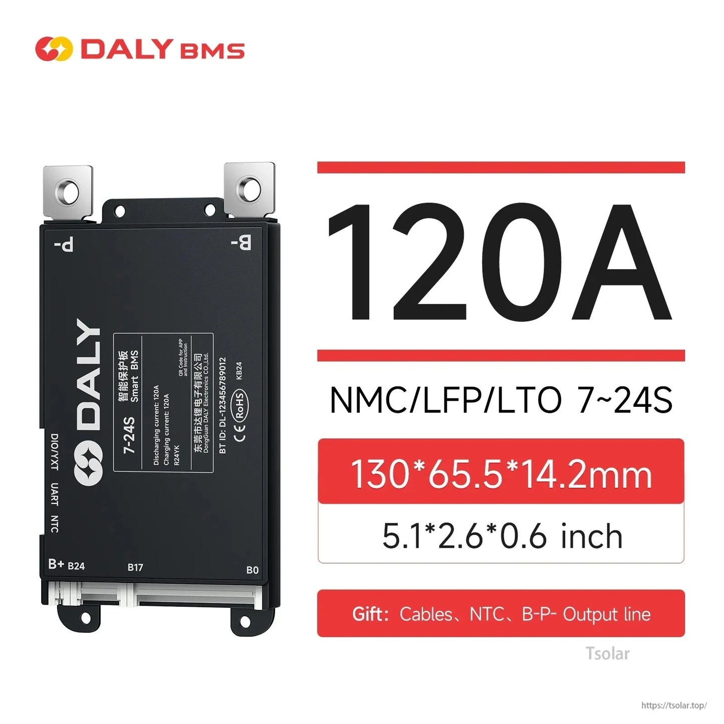
The DALY SMART BMS Y-series 80-120A (YK) is a smart battery management system (BMS) with built-in Bluetooth for real-time monitoring via an app. It supports multiple string ranges (4-8S / 7-17S / 7-24S options) and is designed for lithium battery packs including Li-ion, LiFePO4, and LTO. It provides protection, passive equalization, and supports optional communication/expansion accessories.
Key Features
- Optional string ranges: 4-8S / 7-17S / 7-24S
- Optional current range: 80A / 100A / 120A
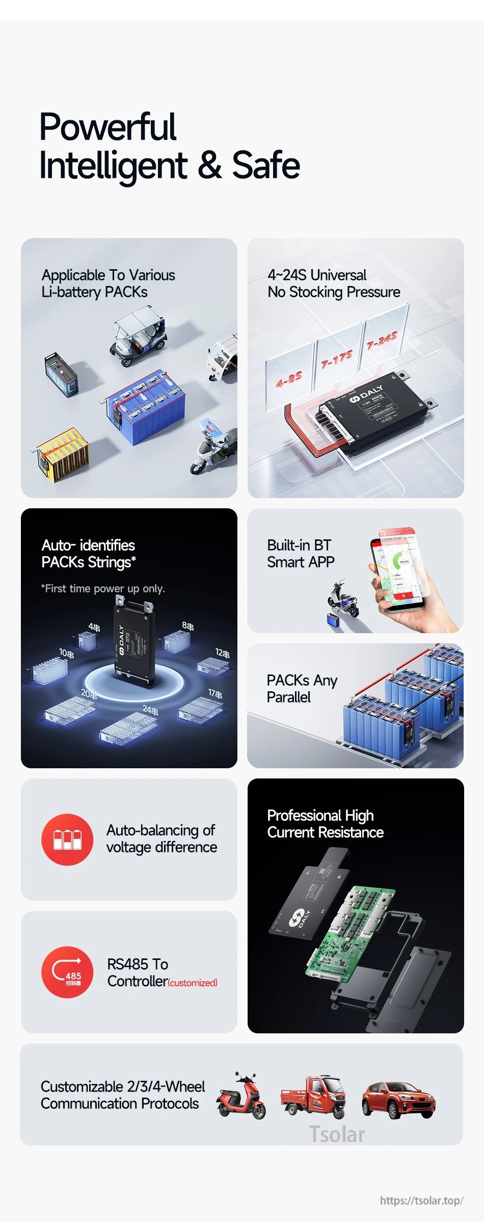
- Built-in Bluetooth: Monitor battery data in real time by connecting to the app
- Smart strings identification: Auto-identifies pack strings on first power-up only
- Passive equalization (passive balance): Balanced Start Voltage 3.4V; Balanced Opening Voltage Difference ≥20mV; Passive Balance Current 100±30mA
- Protection functions: Overcharge, Over-discharge, Overcurrent, Pre-charge, Short circuit, High temperature, Low temperature, Static electricity, Offline
- Communication: Standard communication Uart; customizable communication RS485, SIF
- Parallel current limiting: Integrated 1A parallel current limiting module
- PC software: PC Master supports Windows system
- Bluetooth OS support: Android/iOS/HarmonyOS
- Hardware notes (from provided content): Precise and fast IC; low resistance, high withstand voltage MOSFET; thermal silica for heat dissipation; preset interface and buckle cable for convenient connection
Specifications
| Series / Model | DALY SMART BMS: Y-series 80-120A (YK) |
| Optional strings range | 4-8S / 7-17S / 7-24S |
| Optional current range | 80A / 100A / 120A |
| Size (YK) | 130*65.5*14.2mm |
| B-P- (YK) | 7AWG 150mm (80A/100A); 6AWG 150mm (120A) |
| Cable (YK) | 550mm |
| Battery type | Li-ion / LiFePO4 / LTO |
| String number range (Li-ion) | 4-8 / 7-17 / 7-20S |
| String number range (LiFePO4) | 4-8 / 8-17 / 8-24S |
| String number range (LTO) | 6-8 / 10-17 / 10-24S |
| Charging voltage | N x 4.2V (Li-ion); N x 3.2V (LiFePO4); N x 2.4V (LTO) |
| Operating temperature | -40~85°C |
| Working power | ≤10mA |
| Sleep current | <600uA |
| Sleep time | 3600S |
| Cell sampling voltage | 1.5~4.9V |
| Standard communication | Uart |
| Customizable communication | RS485, SIF |
| Parallel current limiting | Integrated 1A parallel current limiting module |
| Dimensional tolerance | ±0.5mm |
Basic Functions
- Over-charging protection
- Over-discharging protection
- Over-current protection
- Temperature protection
- Disconnect protection
- Short Circuit Protection
- Balance Function
- Short Circuit protection recover
What’s Included
- BMS*1pcs
- Sampling cable*1pcs
- Temperature probe (NTC)*1pcs
- B+ cable *1pcs
- English manual *1pcs
- USB-Uart cable *1pcs
Optional Accessories / Customization (Bulk/OEM)
- UART to USB cable
- Battery Capacity Indicator
- Touch screen LCD
- Soft switch
- Key switch
- RS485 and CAN Communication
- DO/I port for special needs
- Expandable accessories (as listed): display screen, WiFi module, GPS module, parallel module, buzzer, heating module, key switch, etc.
Optional accessories and customized accessories must match the BMS model and be purchased at the same time. For function/parameter/logo customization and OEM requirements, contact customer service at https://tsolar.top/ or service@tsolar.top.
Applications
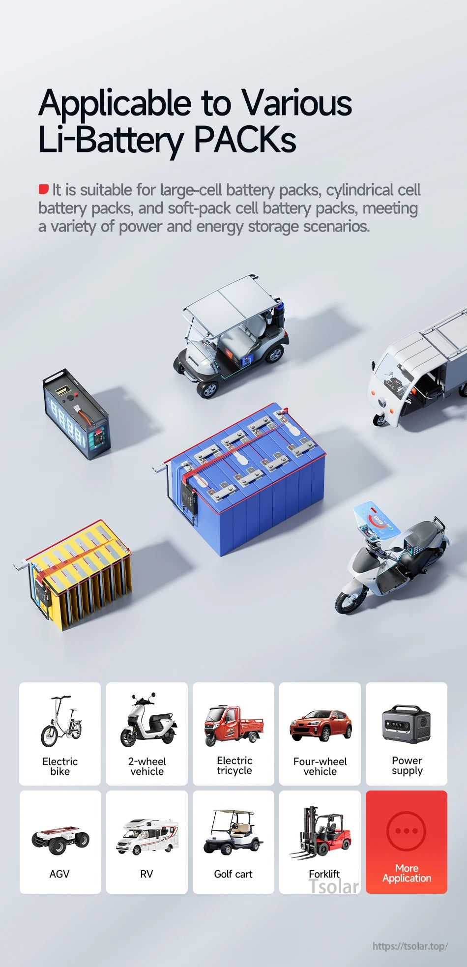
- RV energy storage
- Photovoltaic energy storage
- Home and outdoor energy storage
- Electric vehicles
- Tricycles
- Forklifts
- Tourist vehicles
- Golf cart
Installation Notes (Balance Cable Connection)
Preparation
- Find the total positive and total negative of the battery pack.
- Find B-/P- of BMS.
- Insert temperature probe (NTC) into the BMS.
Welding
- Note: When soldering, the balance cable cannot be inserted into the BMS.
- (1) Weld sampling cables: Start from thin black wire to B- (total negative), then connect each cell's positive in order. Last red wire to B+ (total positive). Note: Do NOT plug into BMS during welding. Insulate unused wires.
- (2) Check voltages: Use multimeter or wire tester to confirm each cell's voltage is normal. Fix any miswiring or poor soldering.
- (3) Weld output wires: Secure B- and P- to BMS with 10N·m torque; weld B- to battery negative. Note: Insulate P- before final connection.
- (4) Plug NTC and sampling cable: Insert NTC, then plug sampling cable to auto-activate BMS.
Voltage Measurement
- Measure whether the battery voltage (B+→B-) is consistent with the output voltage of the BMS (B+ P-).
- If the two voltage values are equal, it means that the BMS is working normally.
How to Choose the Right BMS (Important)
- Battery chemistry match: BMS type and lithium battery type must be in one-to-one correspondence (Li-ion/LiFePO4). Mismatch may cause BMS damage and the battery may not be fully charged and discharged.
- String match: BMS strings and battery strings must be in one-to-one correspondence. Mismatch can lead to BMS and battery burn out.
- Selection method (as provided): load maximum power ÷ (string number of battery × overdischarge voltage) × coefficient. Depending on the battery usage scenario, the coefficient value is different.
Details


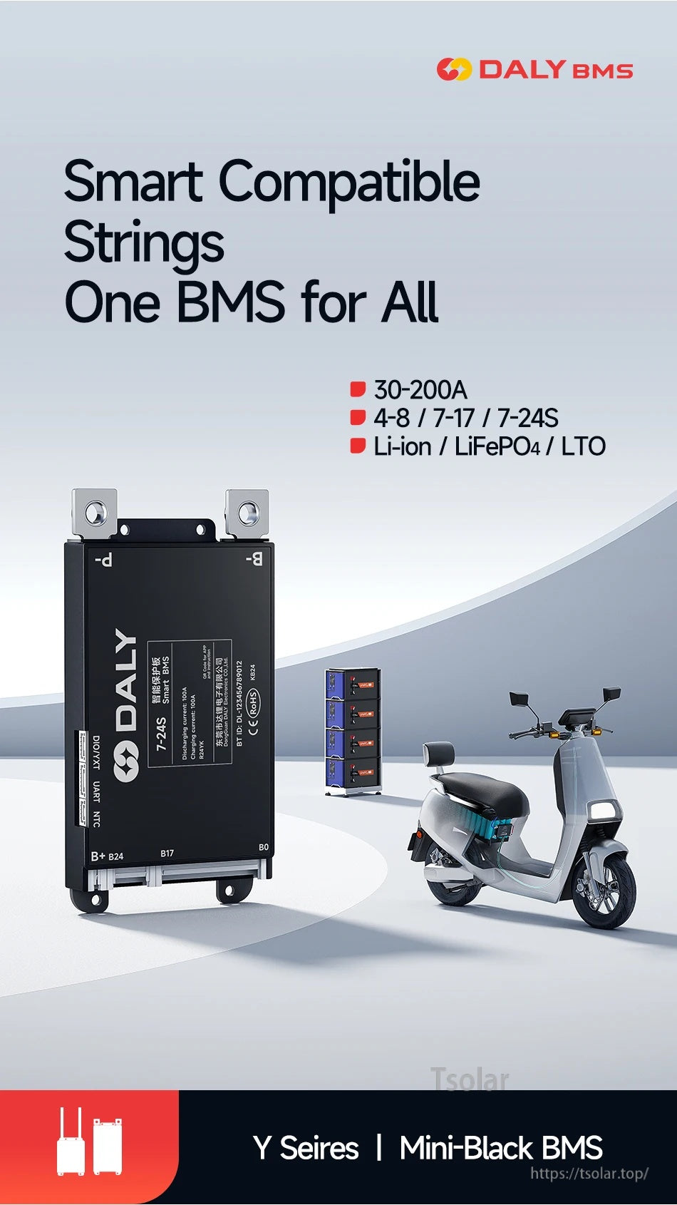
A smart battery management system for lithium packs, designed to cover multiple string-count options in one platform.
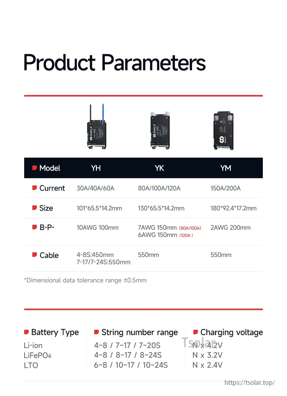
Choose the YK version in 80A, 100A, or 120A, with the listed board size and cable lengths for your build.
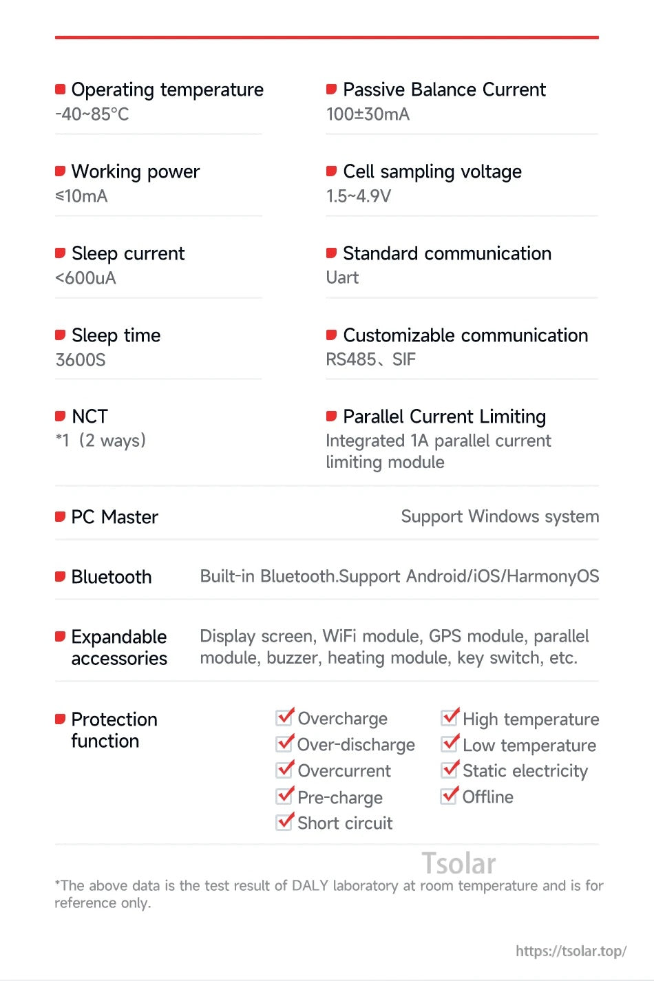
Detailed electrical specs include passive balance current, sleep current, communications (UART with optional RS485/SIF), and built-in protections.

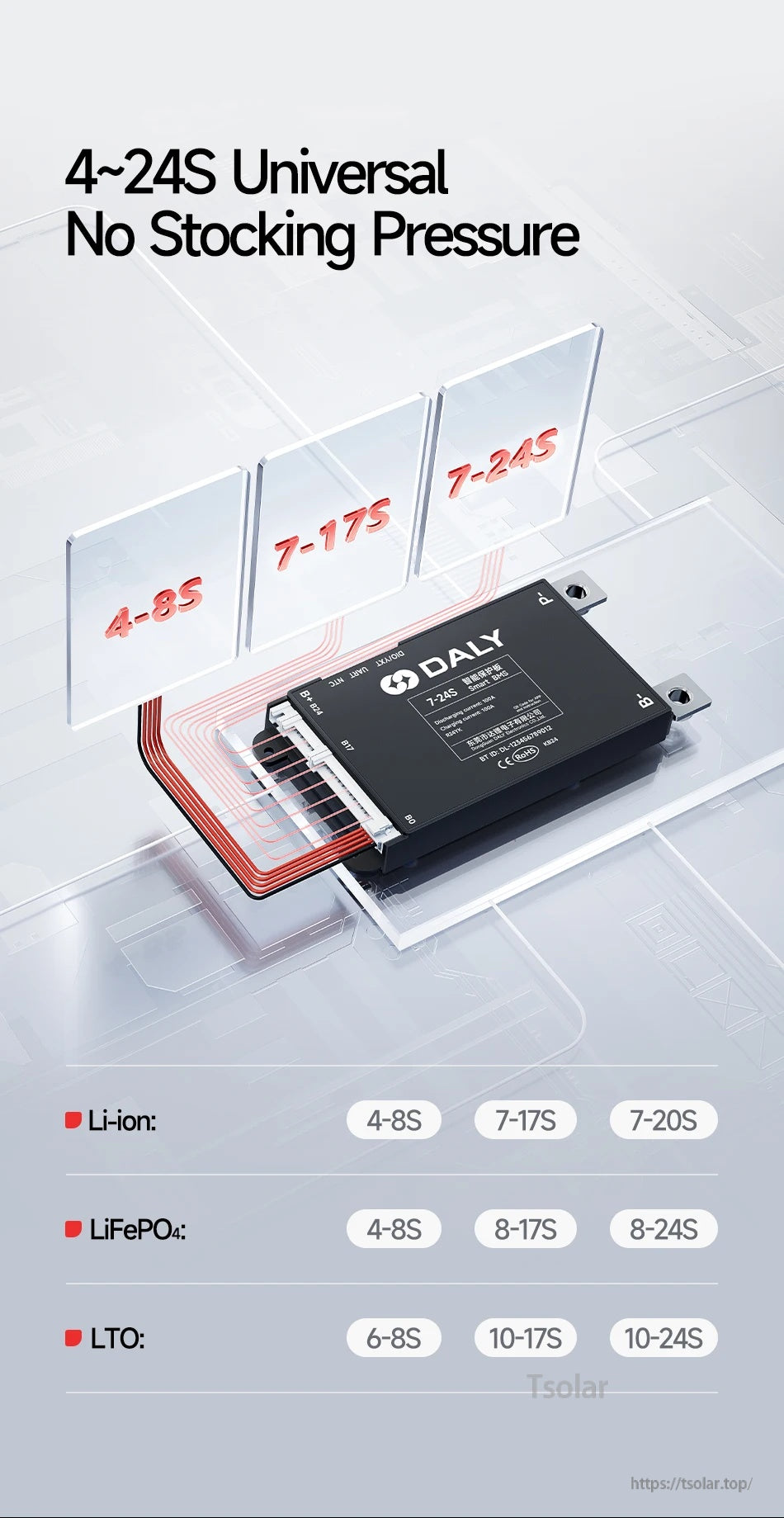
Multiple string ranges support Li-ion, LiFePO4, and LTO packs, helping standardize parts across different battery builds.
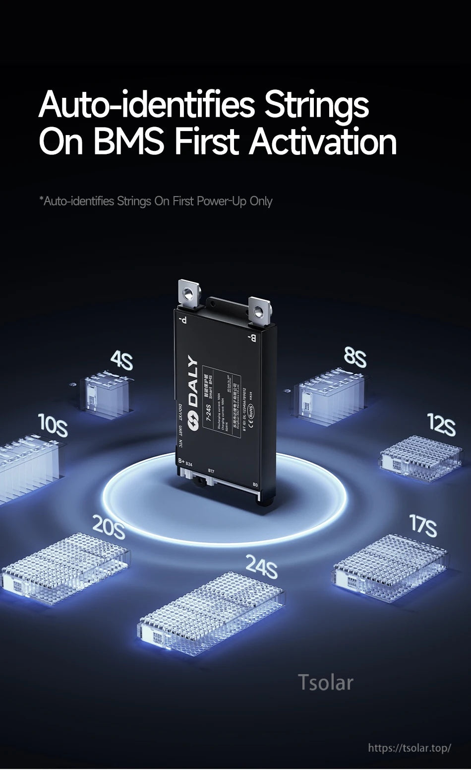
Initial power-up can auto-detect the pack string count to speed setup during installation.
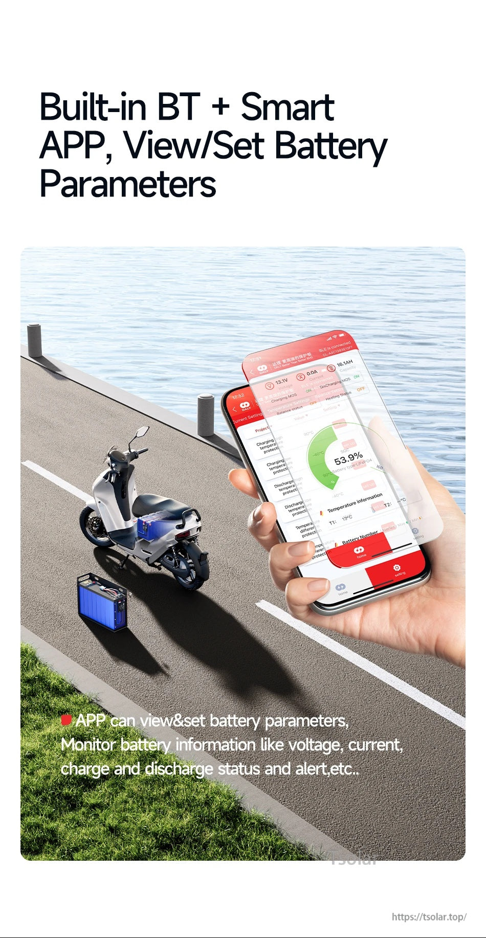
Built-in Bluetooth connects to the app for real-time monitoring and parameter settings on supported mobile devices.
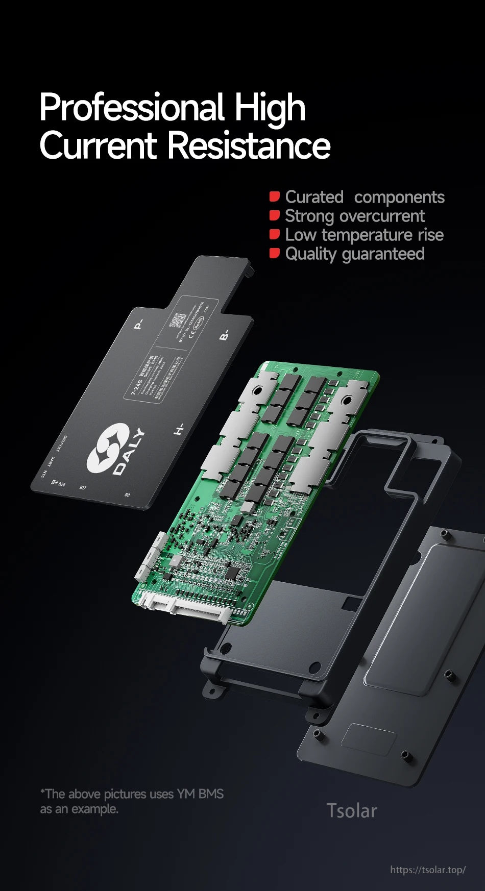
Internal structure emphasizes robust power components and enclosure design; visuals use a comparable series example.

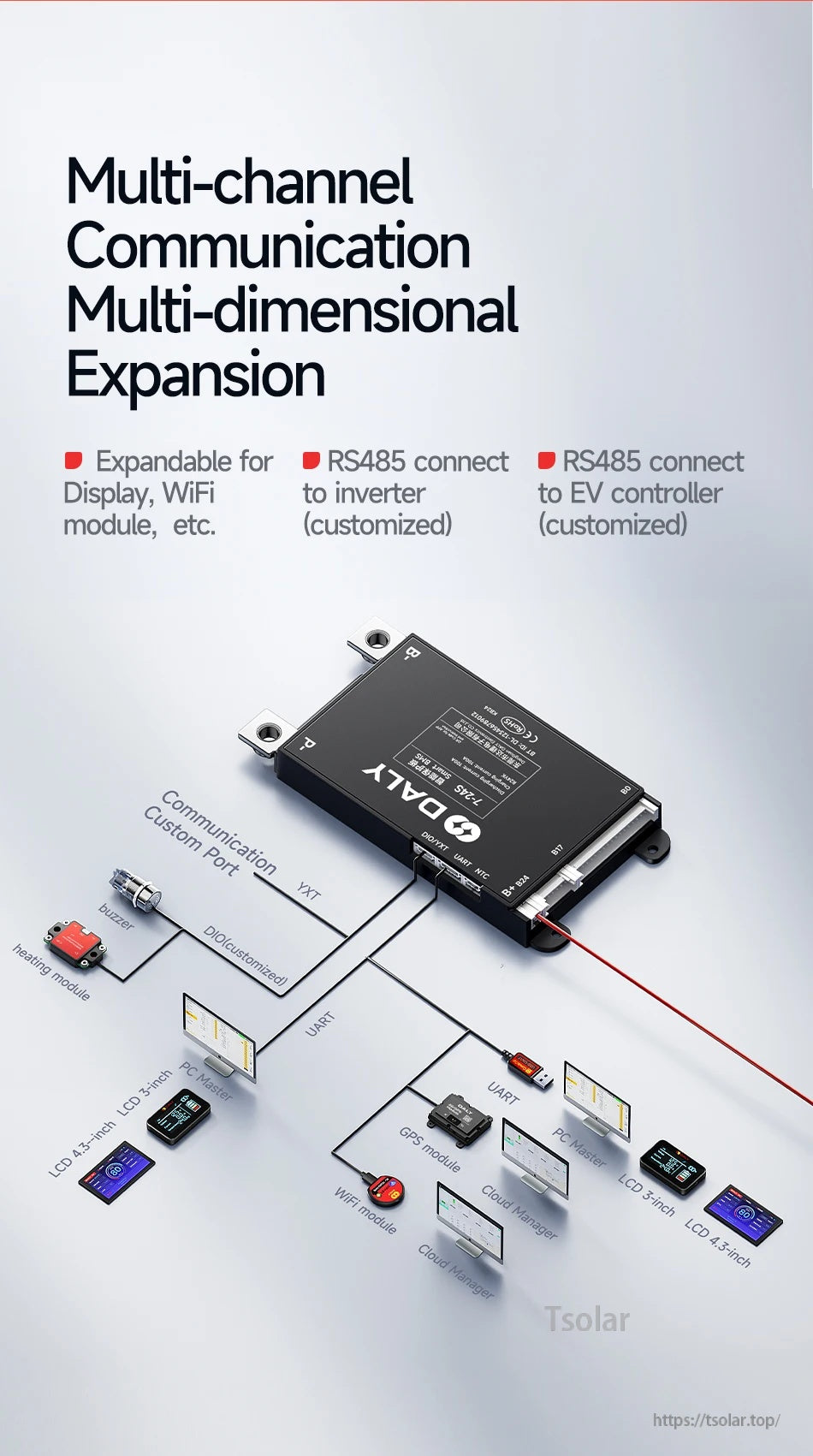
Optional expansion accessories and communication ports make it easier to integrate monitoring, alarms, and controller connections.
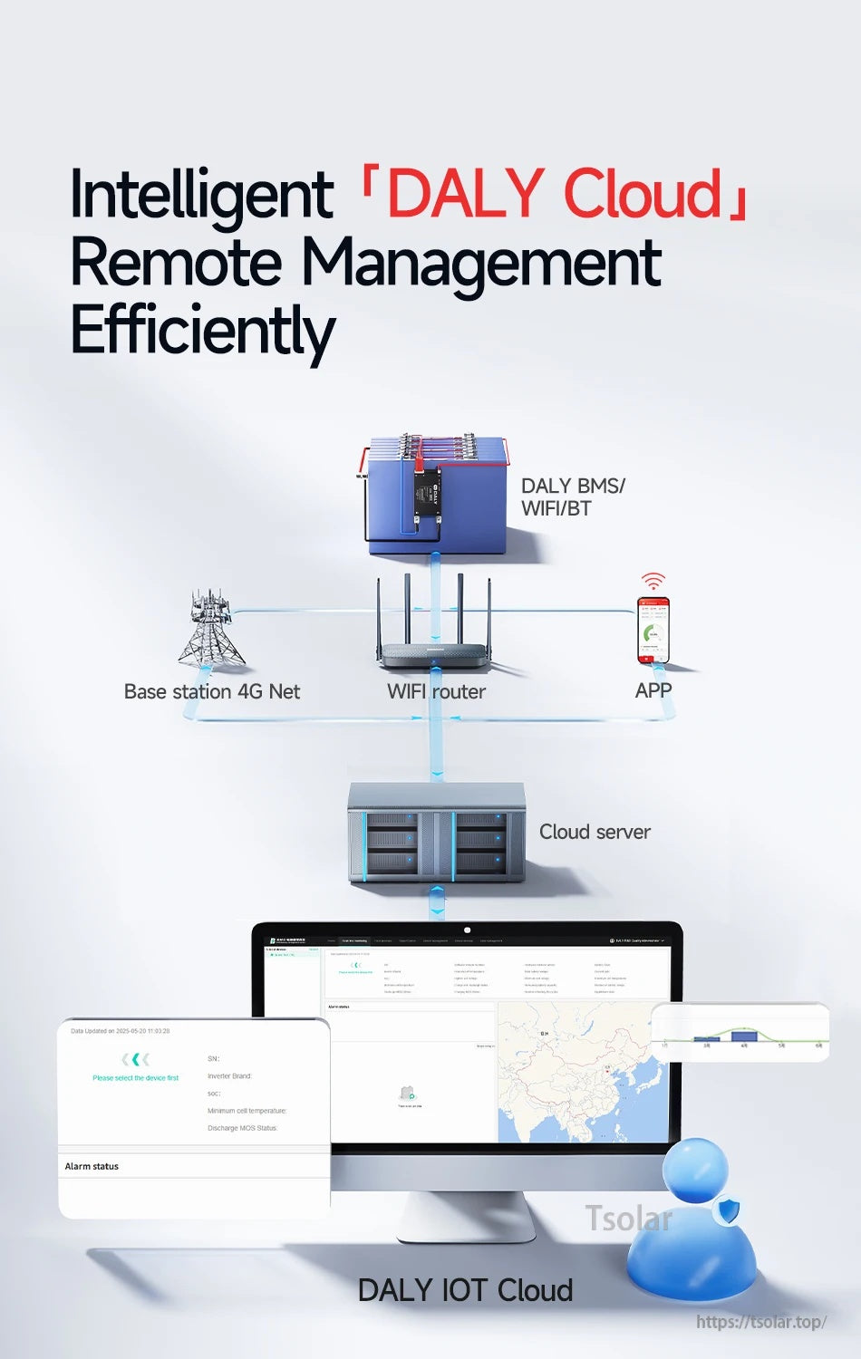
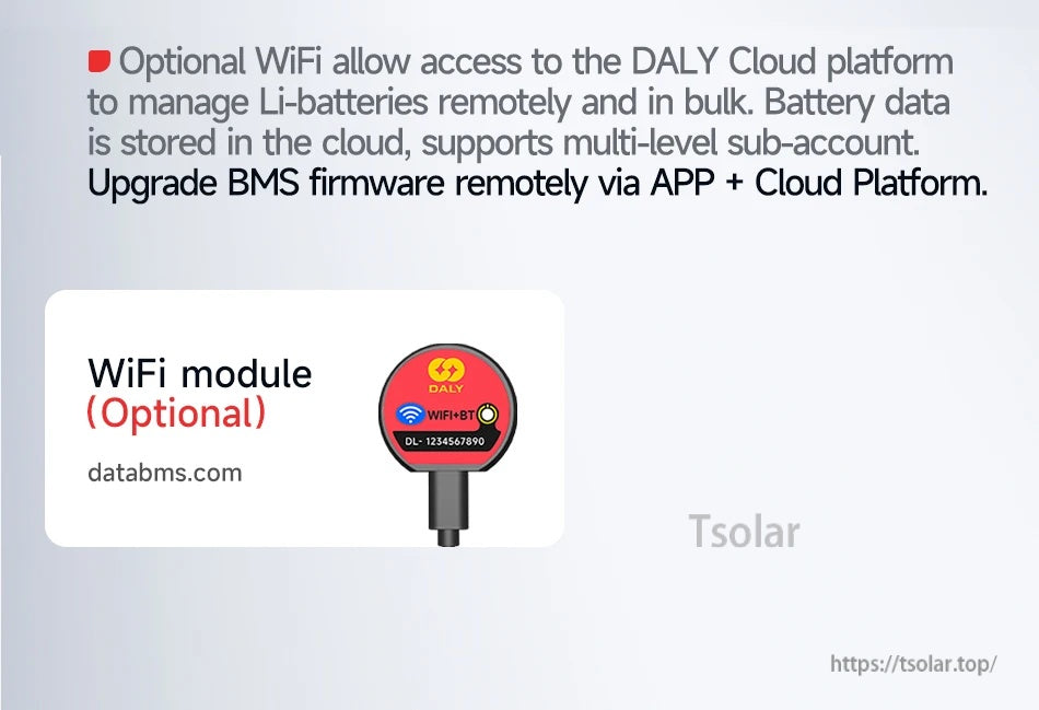
Remote fleet-style monitoring is available through DALY Cloud when used with supported networking accessories.
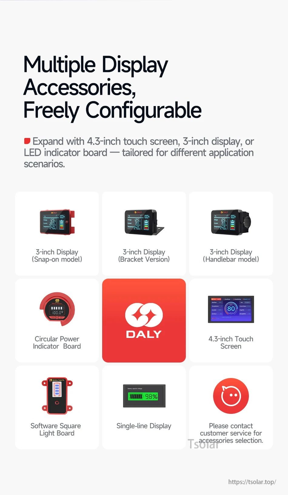
Add a dedicated display or indicator to keep key battery data visible on the vehicle or enclosure.

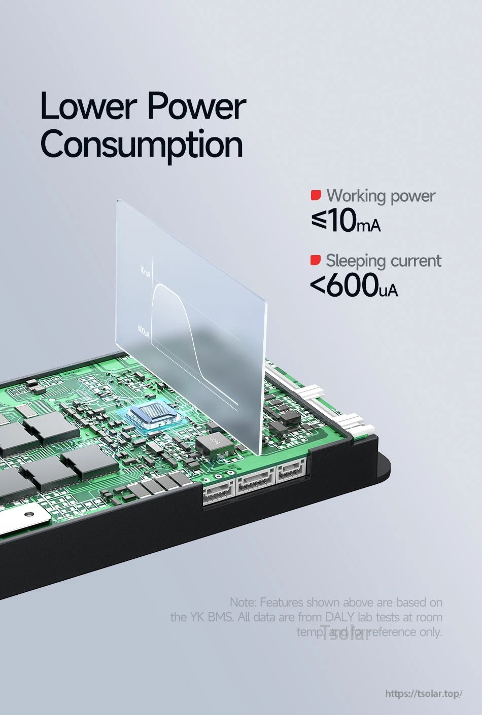
DALY Smart BMS is designed for low power draw, with listed working power ≤10mA and sleeping current under 600µA.
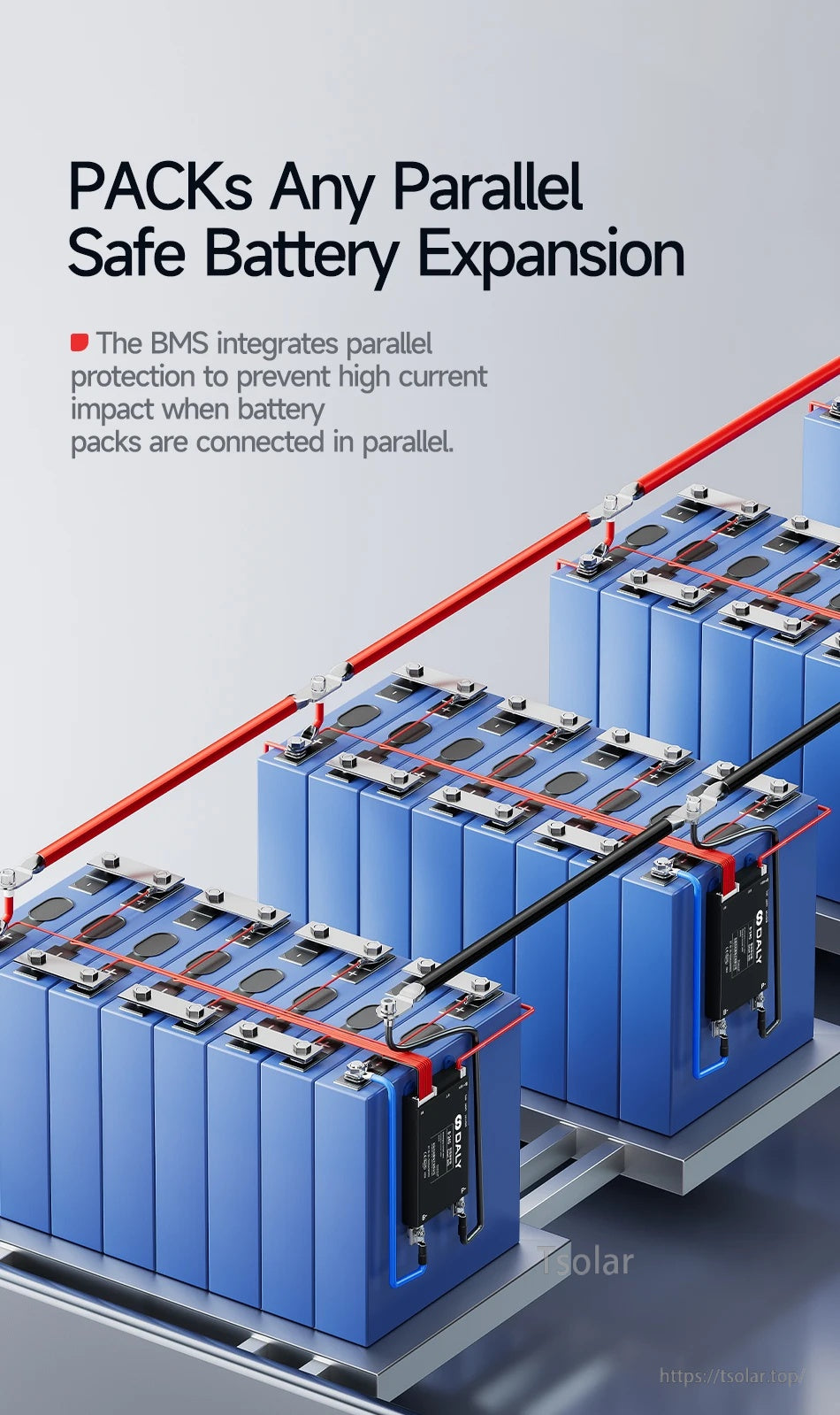
The DALY Smart BMS is designed for parallel battery pack expansion with integrated parallel protection to reduce high-current impact.
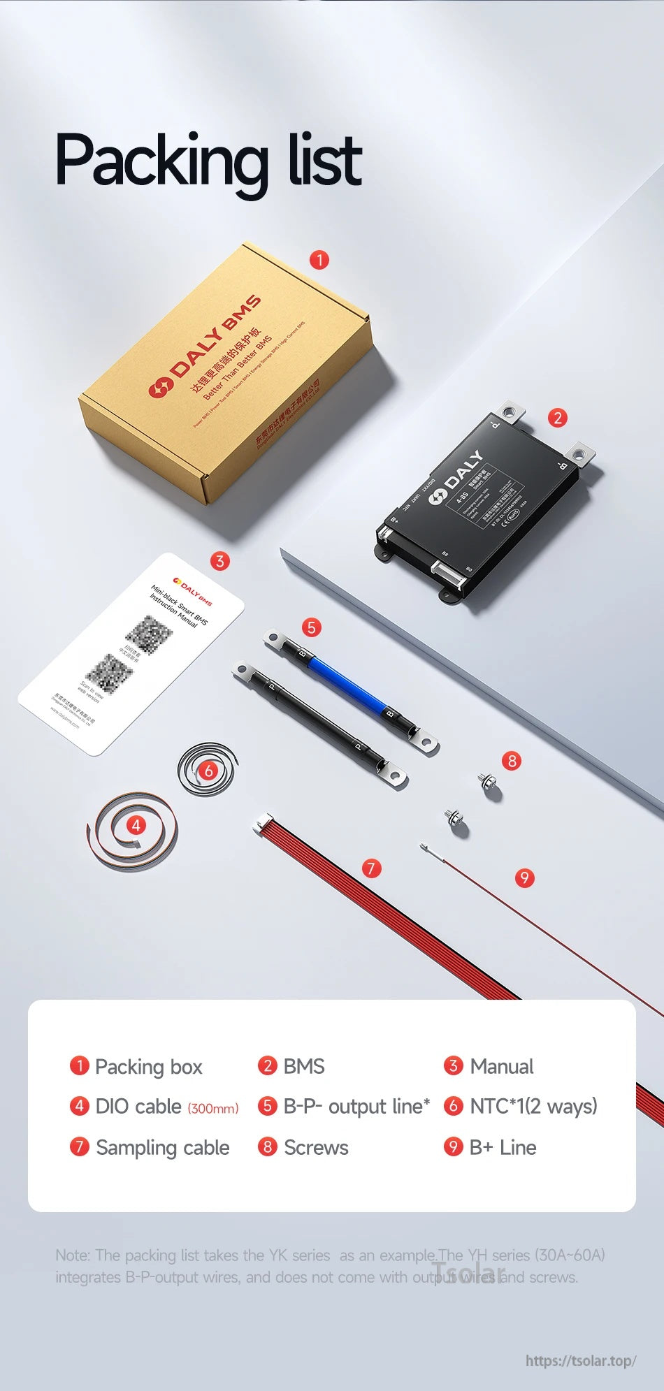
The DALY Smart BMS package includes the BMS unit, manual, sampling cable, DIO cable, NTC sensor leads, B+ line, and mounting screws.
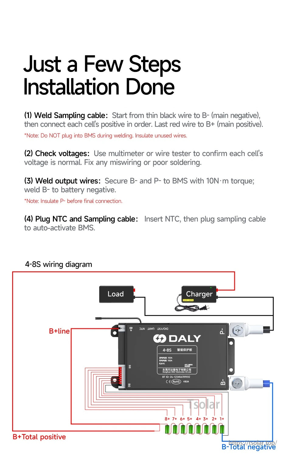
DALY Smart BMS wiring guidance outlines the 4–8S connections for charger, load, B+/B- leads, and the cell sampling harness.
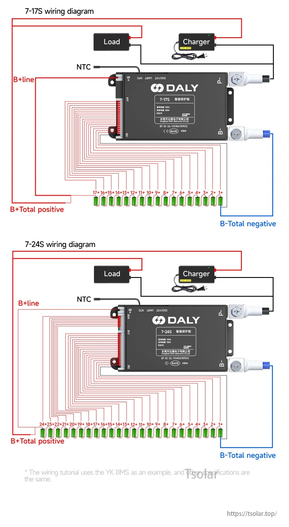
DALY Smart BMS wiring diagrams map the charger/load connections, B+ and B- terminals, NTC lead, and the numbered balance-wire order for 7–17S or 7–24S battery packs.

The DALY Smart BMS Mini-Black BMS Y Series branding is presented on a simple red header graphic.

DALY Smart BMS support includes customizable app, PC master, and cloud manager features with Bluetooth/WiFi hardware and software options.

DALY Smart BMS development is backed by an engineering team reviewing circuit designs and test data in a lab setting.

DALY’s intelligent production base supports large-scale Smart BMS manufacturing with dedicated testing and assembly lines.
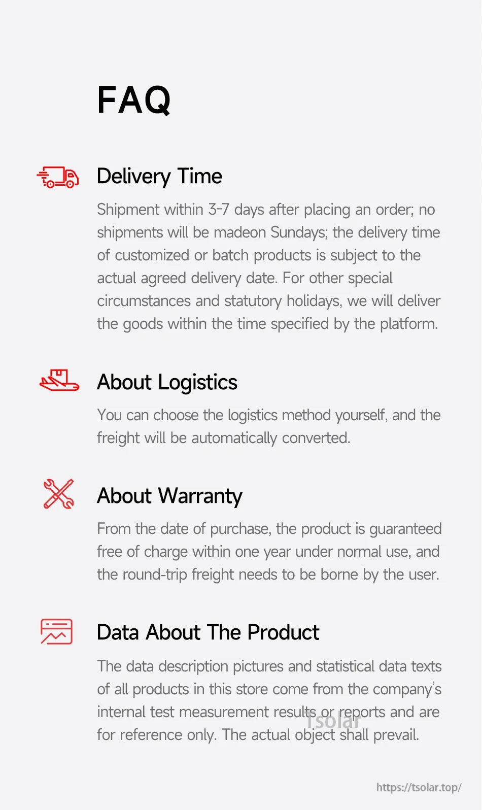
DALY Smart BMS ordering details cover delivery time estimates, logistics options, warranty terms, and product data references.