Overview
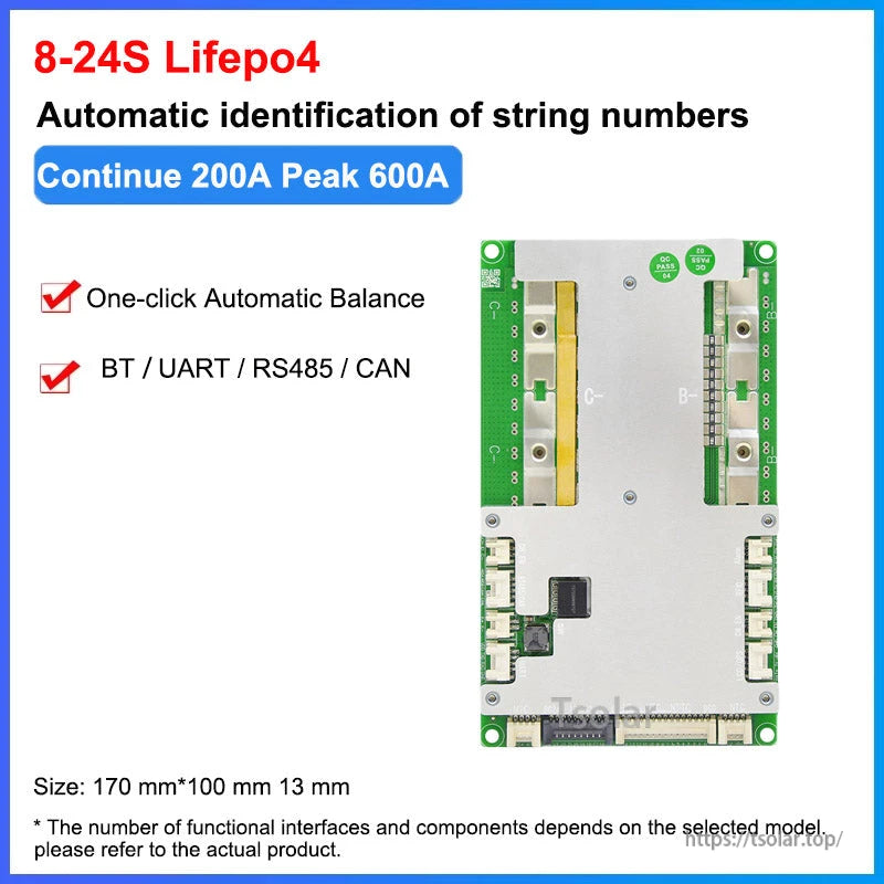
The JBD (Jiabaida) SP24S004 is a Smart Battery Management System (Smart BMS) for 3.2V LiFePO4 and 3.7V Li-ion (NMC) battery packs from 8S to 24S. It supports real-time monitoring and parameter configuration via app/PC tools, with communication options including UART, RS485, and CAN (product materials also mention GPS as an optional communication type). Bluetooth is supported via an external Bluetooth module.
Key Features
- Supported chemistries: 3.7V Li-ion (NMC) / 3.2V LiFePO4 lithium battery
- Supported strings: 8S/9S/10S/11S/12S/13S/14S/15S/16S/17S/18S/19S/20S/21S/22S/23S/24S
- Multiple communication interfaces: UART / RS485 / CAN (optional communication types shown: RS485, UART, CAN, GPS)
- Bluetooth supported: External Bluetooth (module may be required)
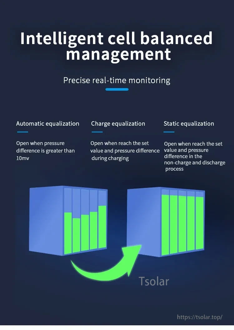
- Cell balancing: Charge and discharge common port with balance function; equalization modes described as automatic/charge/static equalization
- Temperature sensing: Five temperature sensors (4 external + 1 internal); board callouts show built-in NTC and external NTC connections
- History storage function: Yes
- Pre-discharge function: Yes
- Sleep behavior: After a static delay of 2 minutes, it enters the sleep state
- Real-time clock (RTC) feature: Records charge, discharge, and protection information
- Protection functions (listed): Overcharge, over-discharge, overcurrent, over temperature sensor, short circuit, overvoltage
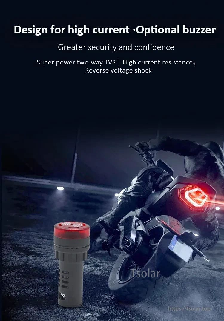
- High-current design notes shown: Super power two-way TVS; reverse voltage shock; optional alarm drive; optional buzzer
- Build/thermal notes shown: Double-sided aluminum alloy heat sink; “extreme heat dissipation structure” text mentions six high-conductivity copper bars and thermal silicone fitting
Specifications
| Product name | Battery Management System |
| Type | Smart BMS |
| Model | SP24S004 |
| Size | 170mm * 100mm * 13mm |
| Strings | 8S-24S |
| Applicable battery type | 3.7V Li-ion (NMC) / 3.2V LiFePO4 |
| Voltage (general listing) | 24V 36V 48V 60V 72V |
| String voltage reference (LiFePO4) | 8S 24V / 12S 36V / 16S 48V / 20S 62V / 24S 72V |
| String voltage reference (NMC) | 13S 48V / 14S 52V / 16S 60V / 20S 72V / 24S 88V |
| Current (range) | 40A-200A |
| Continuous / peak current options |
Continuous 40A, peak 80A, continue 1s; Continuous 60A, peak 120A, continue 1s; Continuous 100A, peak 200A, continue 1s; Continuous 150A, peak 300A, continue 1s; Continuous 200A, peak 400A, continue 1s; |
| Temperature sensors | 1pc internal, 4pcs external (five sensors total shown) |
| Communication | UART / RS485 / CAN |
| Bluetooth support | Yes (external Bluetooth) |
| Support automatic identification of string number | Yes |
| Support display | Yes |
| Display type | UART/RS485 Display |
| Balance function | Charge and discharge common port with balance function |
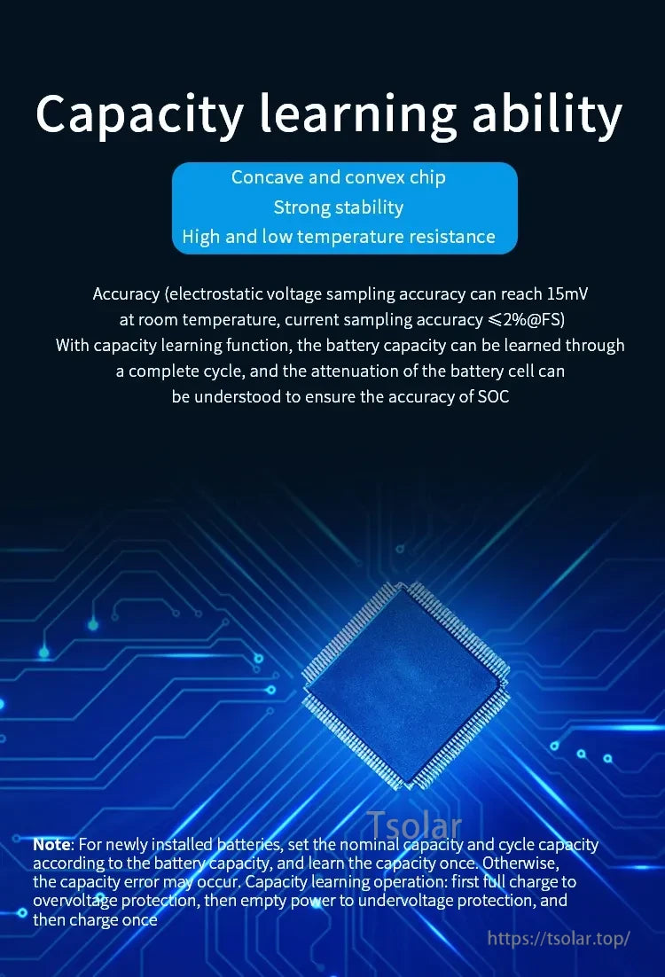
| Sampling accuracy (shown) | Voltage sampling accuracy can reach 15mV (room temperature); current sampling accuracy <= 2%@FS |
Software & Monitoring
- Mobile app (Bluetooth): App name: XiaoxiangElectric; supports iOS and Android. Download: http://www.jiabaida.com/appdown/index.html
- PC tool (UART or RS485): JBD PC Tool Box. Download: https://jbdtools.oss-cn-beijing.aliyuncs.com/packfile/JBDTools.zip
- UART or RS485 LCD display: Monitoring parameters on an LCD display is supported.
- Port note: UART and BT use the same port and cannot be used at the same time.
- Parameter note: Smart BMS supports converting Li-ion and LiFePO4 parameters via the app/PC tool (within the specified range).
Wiring Notes (Balance Wire Shorting Method)
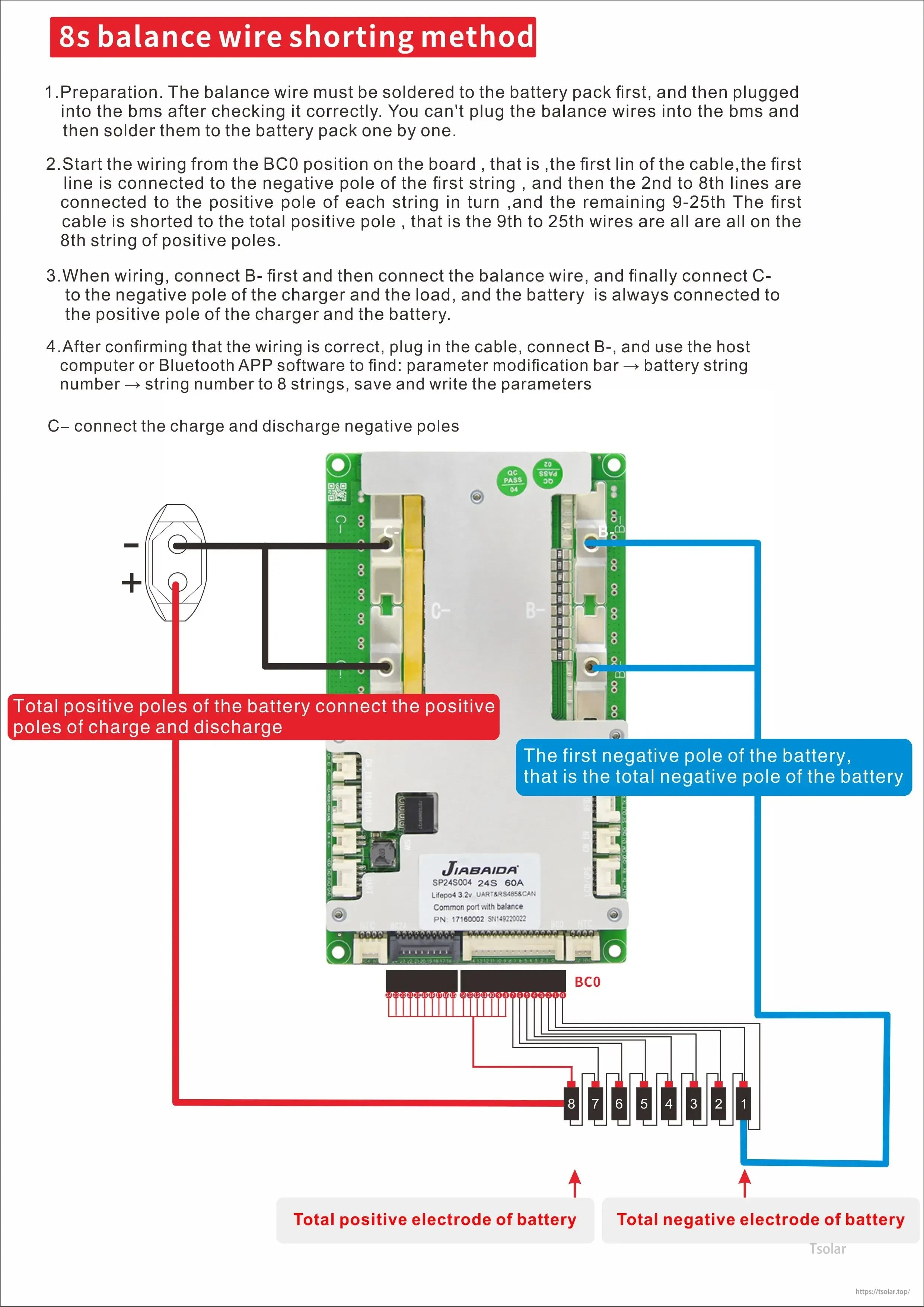
8S balance wire shorting method
- Preparation: The balance wire must be soldered to the battery pack first, and then plugged into the BMS after checking it correctly. The balance wires cannot be plugged into the BMS and then soldered to the battery pack one by one.
- Wiring start: Start from the BC0 position on the board. The first line of the cable is connected to the negative pole of the first string; the 2nd to 8th lines are connected to the positive pole of each string in turn; the remaining 9-25th lines: the first cable is shorted to the total positive pole, and the 9th to 25th wires are all on the 8th string of positive poles.
- Connection order: When wiring, connect B- first, then connect the balance wire, and finally connect C- to the negative pole of the charger and the load. The battery is always connected to the positive pole of the charger and the battery.
- Parameter setting: After confirming that the wiring is correct, plug in the cable, connect B-, and use the host computer or Bluetooth APP software to find: parameter modification bar -> battery string number -> string number to 8 strings; save and write the parameters.
C- connects the charge and discharge negative poles.
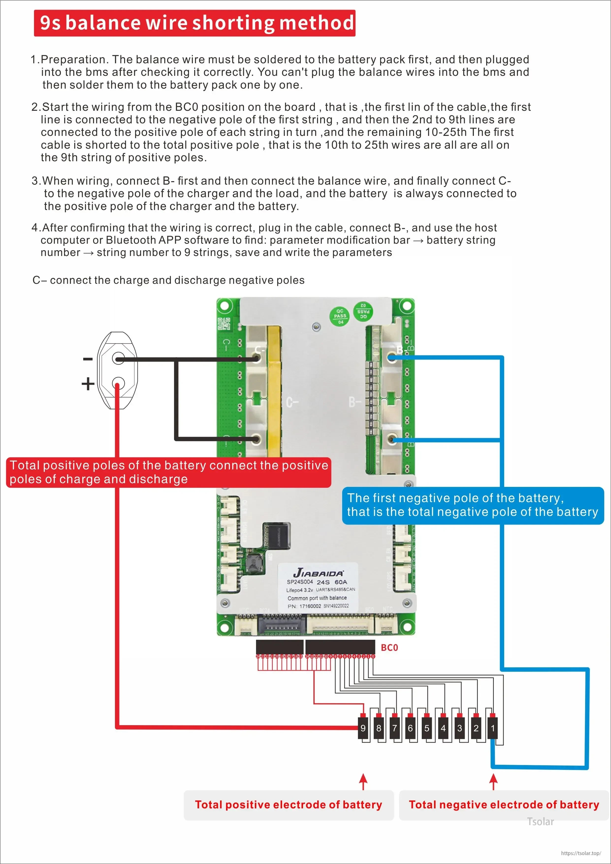
9S balance wire shorting method
- Preparation: The balance wire must be soldered to the battery pack first, and then plugged into the BMS after checking it correctly. The balance wires cannot be plugged into the BMS and then soldered to the battery pack one by one.
- Wiring start: Start from the BC0 position on the board. The first line of the cable is connected to the negative pole of the first string; the 2nd to 9th lines are connected to the positive pole of each string in turn; the remaining 10-25th lines: the first cable is shorted to the total positive pole, and the 10th to 25th wires are all on the 9th string of positive poles.
- Connection order: When wiring, connect B- first, then connect the balance wire, and finally connect C- to the negative pole of the charger and the load. The battery is always connected to the positive pole of the charger and the battery.
- Parameter setting: After confirming that the wiring is correct, plug in the cable, connect B-, and use the host computer or Bluetooth APP software to find: parameter modification bar -> battery string number -> string number to 9 strings; save and write the parameters.
C- connects the charge and discharge negative poles.
What’s Included
- BMS
- BT module
- Balance wires
Bluetooth type is described as external Bluetooth; if a separate external Bluetooth accessory is required for a specific configuration, confirm before ordering.
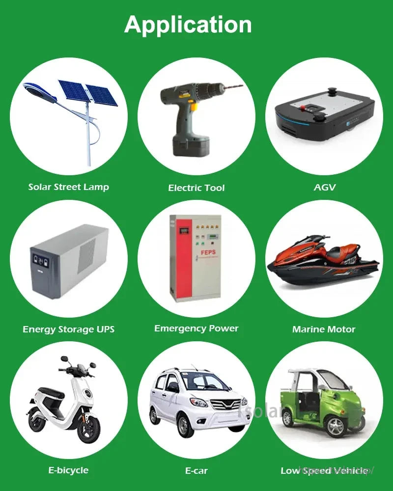
Applications
- Power battery packs; energy storage lithium batteries
- E-bike, e-motorcycle, e-scooter, e-tricycle, mobility scooter, low-speed vehicle, e-car
- Electric tools
- Solar street lamp
- AGV
- Energy Storage UPS, emergency power
- Marine motor
- Home energy storage
For wiring diagrams, configuration confirmation (current rating, communication option, Bluetooth module), and technical questions, contact service@tsolar.top or visit https://tsolar.top/.
Details

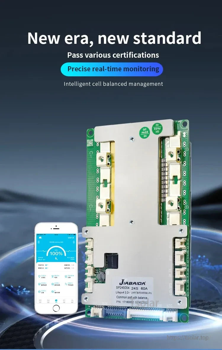
Monitor pack status in real time and adjust key parameters using the XiaoxiangElectric app (external Bluetooth module required).
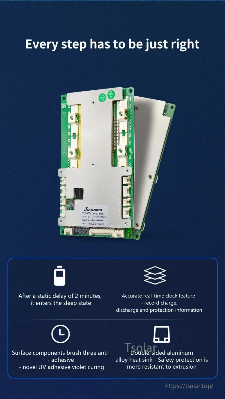
Built-in RTC logging and automatic sleep after a short idle delay help support long-term pack management.

A double-sided aluminum heat sink design helps move heat away from high-current components for more stable operation.
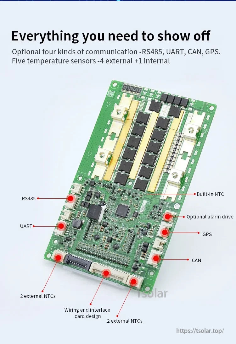
Choose UART, RS485, or CAN communication (GPS shown as an option), with connections for one internal and four external temperature sensors.

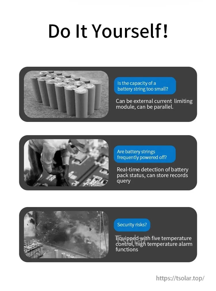
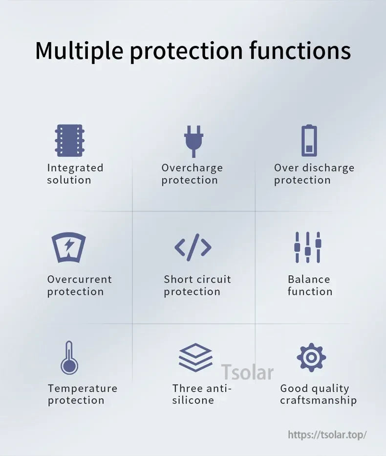
Comprehensive protections cover over/under-voltage, overcurrent, short-circuit, temperature, and balancing support.
Wiring reference for balance leads and main pack connections; follow the correct string count and polarity before powering on.


JBD SP24S004 smart BMS wiring for a 13S pack uses numbered balance leads (B0–B13) plus clear charge/discharge positive and negative terminal connections.
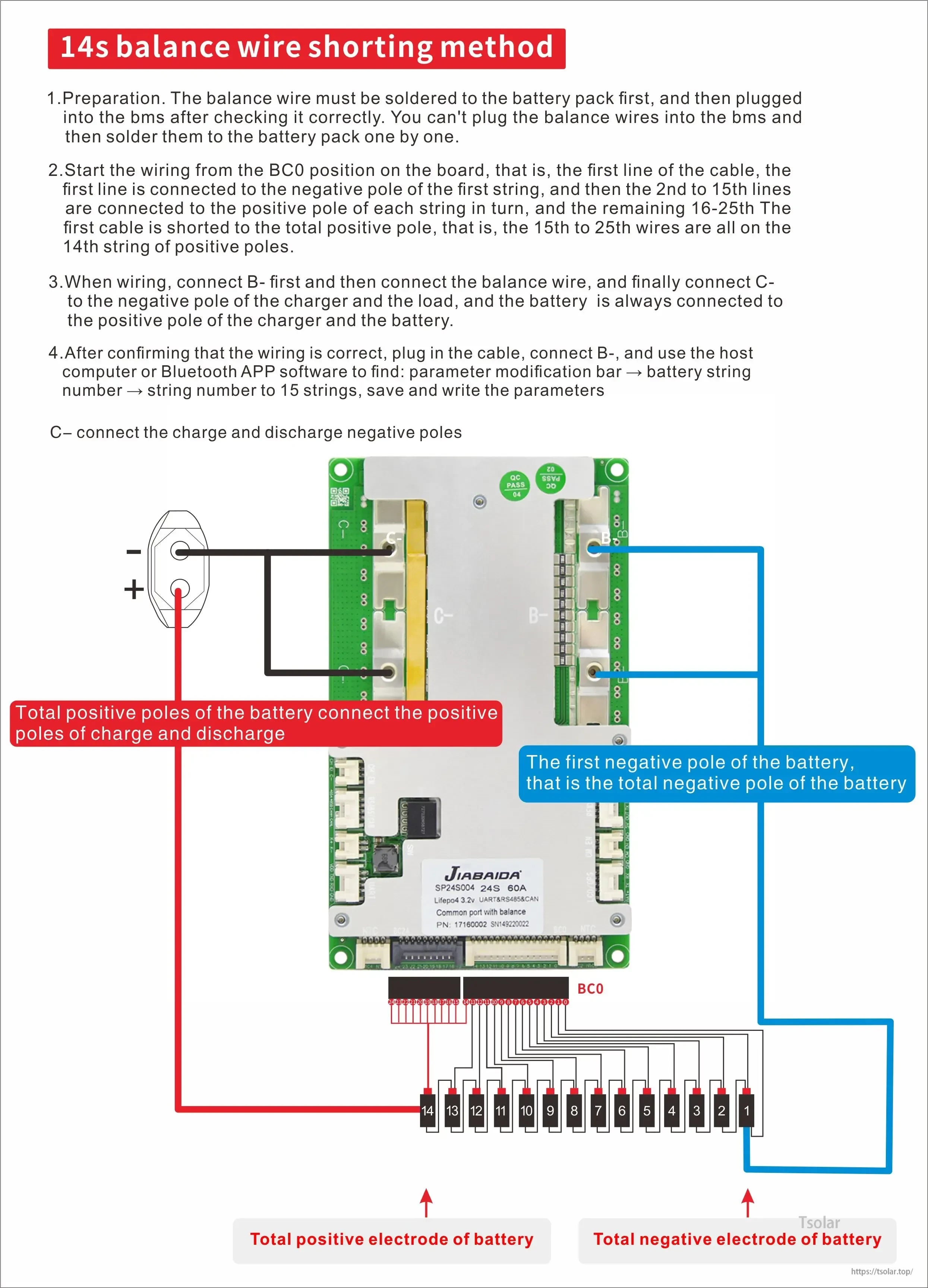
The JBD SP24S004 smart BMS wiring layout shows the 14S balance lead order plus the main pack positive and negative connections for charge and discharge.
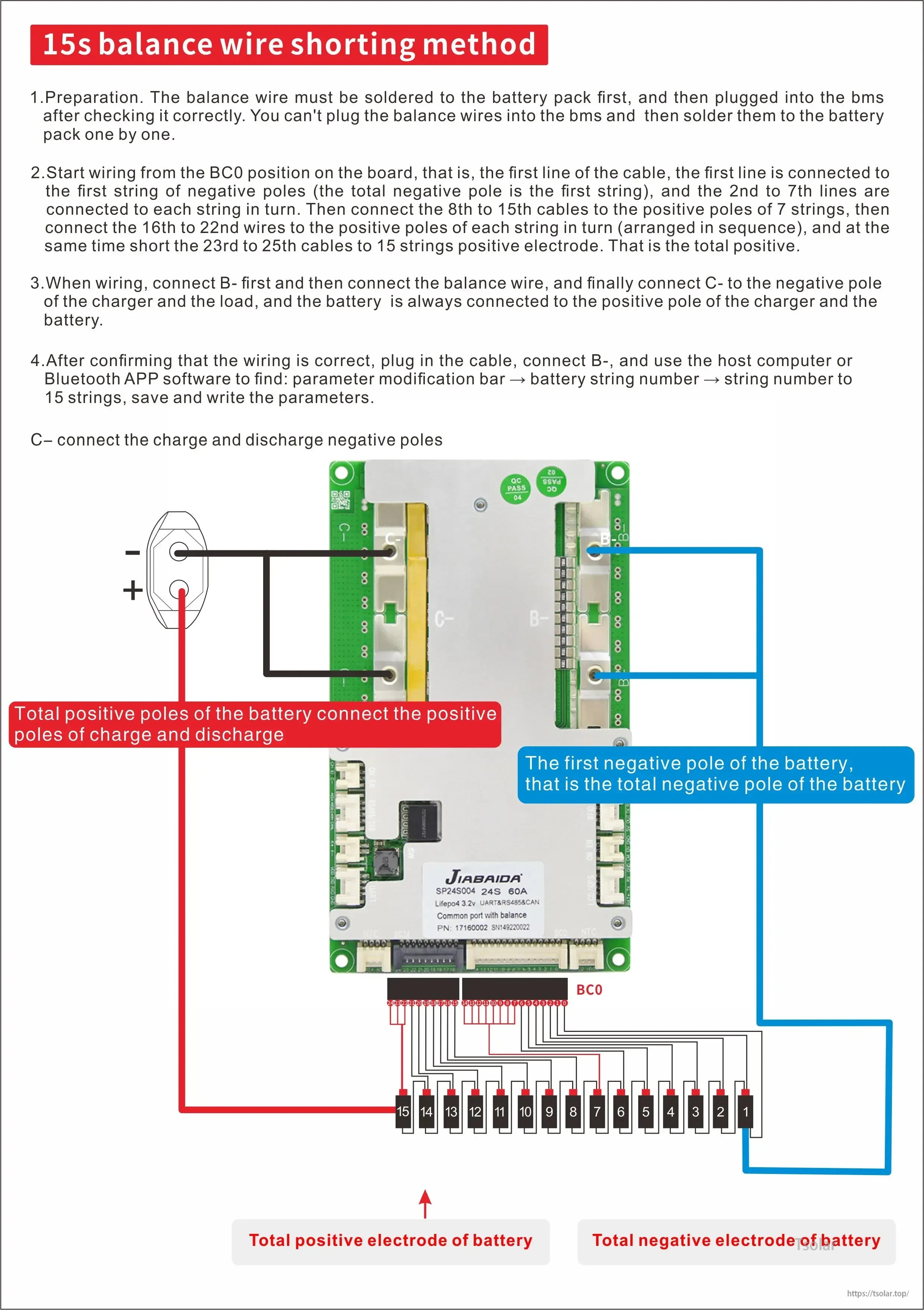
JBD SP24S004 smart BMS wiring uses a 15S balance lead sequence (B0 to B15) plus clear charge/discharge positive and negative terminals for correct pack connection.
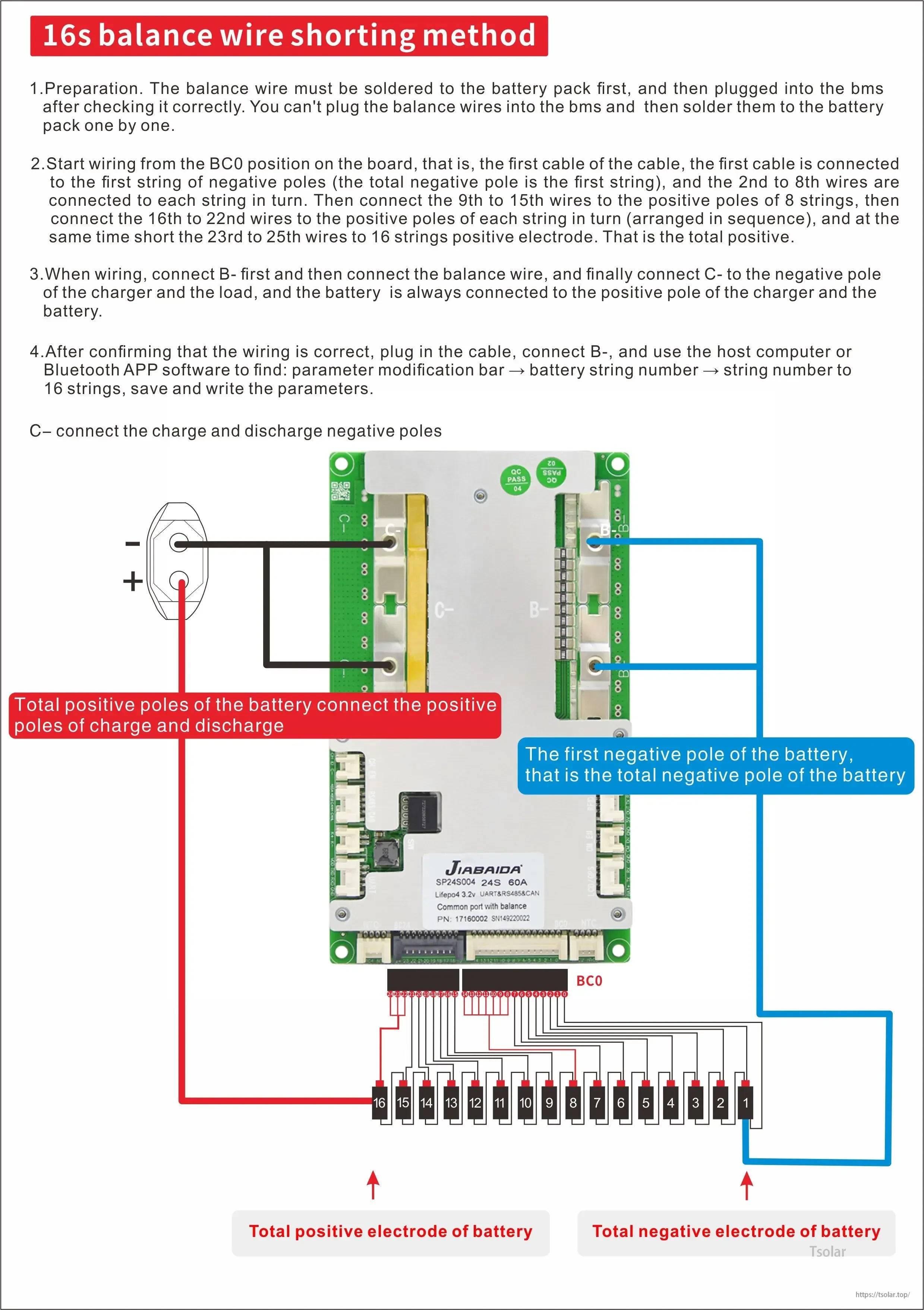
The JBD SP24S004 Smart BMS wiring layout helps connect 16S balance leads plus the main charge and discharge terminals correctly.
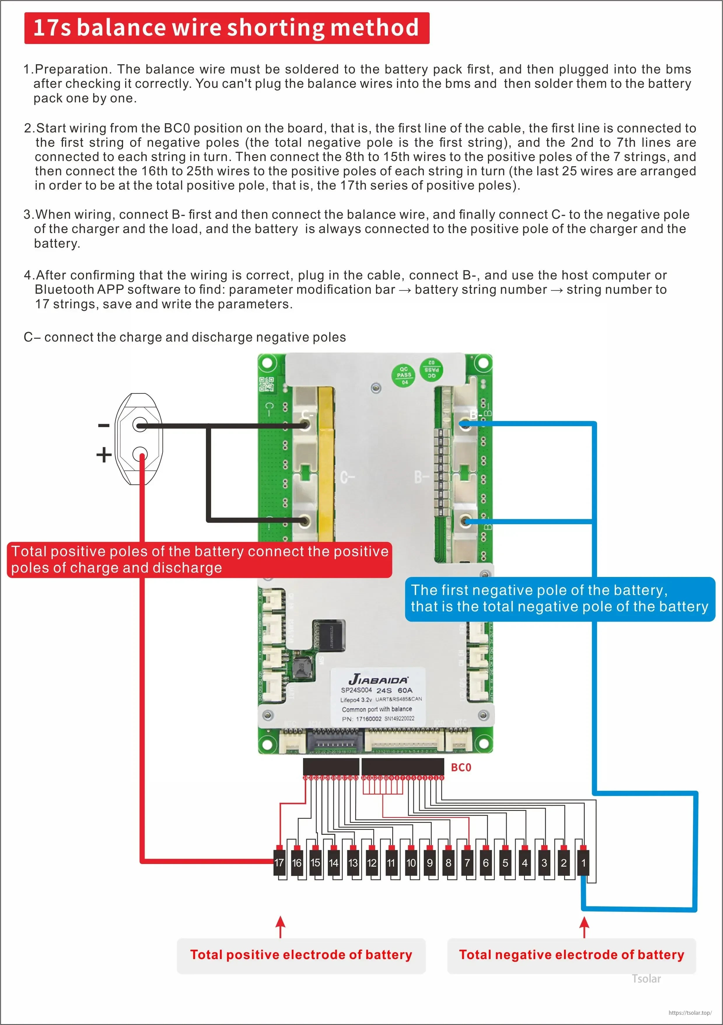
The JBD SP24S004 smart BMS uses a 17S balance lead harness plus C- and P- terminals to connect the pack negative and charge/discharge negatives correctly.
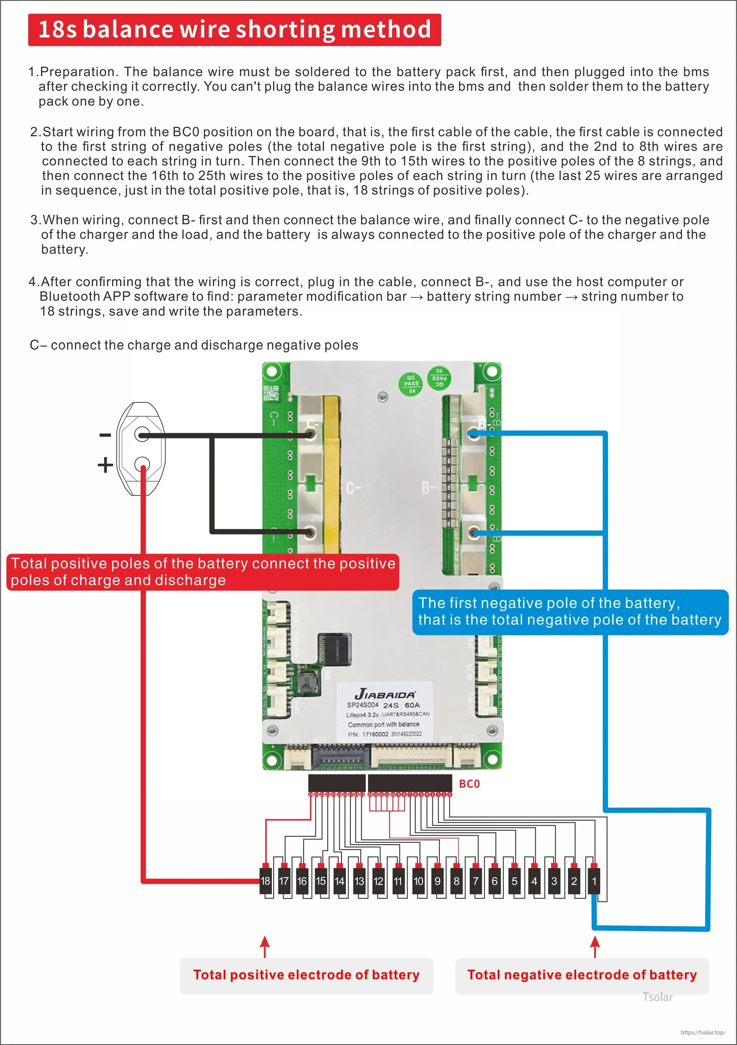
JBD SP24S004 Smart BMS wiring uses an 18S balance lead harness plus clear B- and P-/C- connections to the battery and load/charger.

The 19S balance wire connection order and shared charge/discharge negative wiring help prevent errors when installing the Smart BMS.
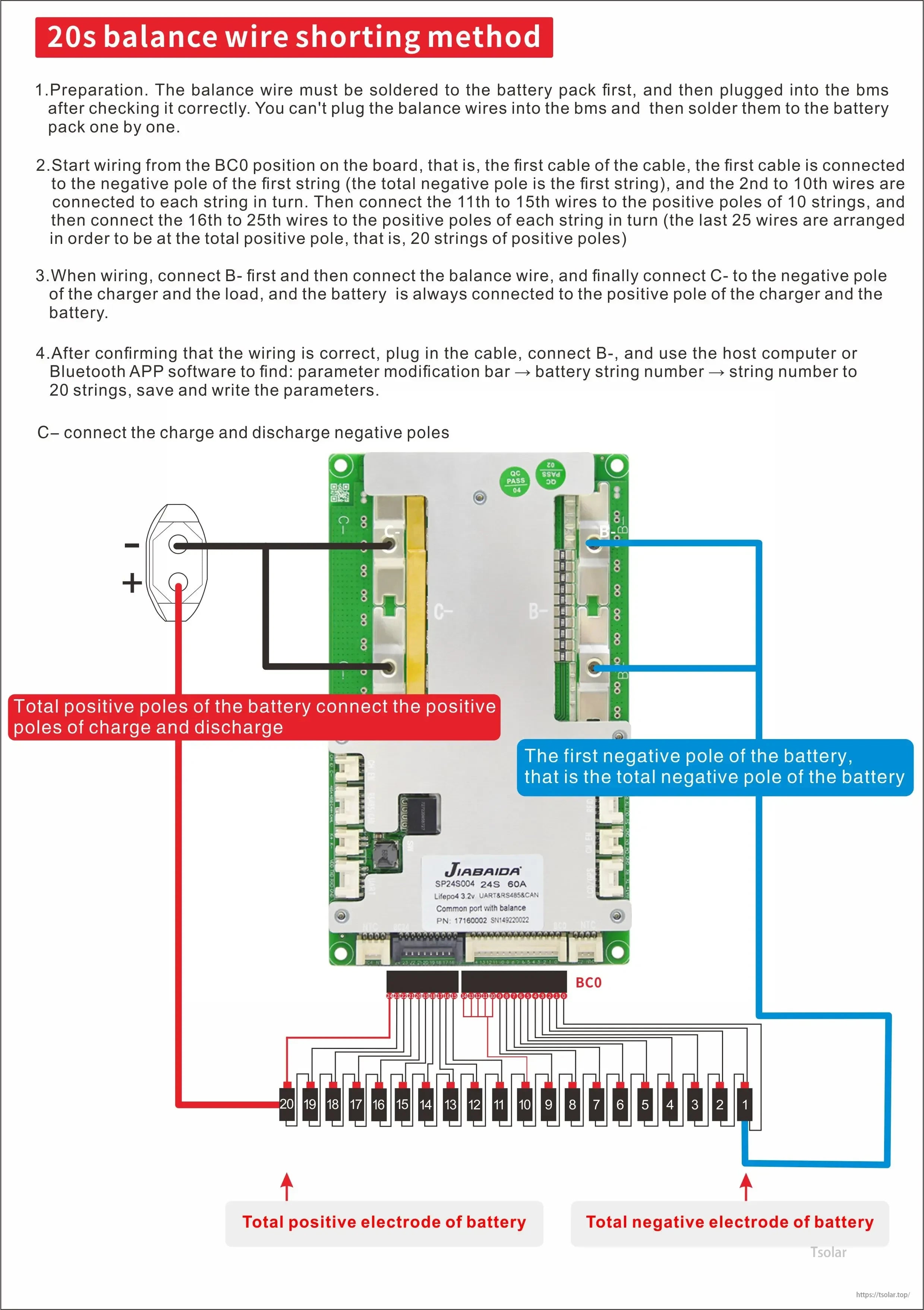
The JBD SP24S004 smart BMS wiring guide lays out the 20S balance lead sequence and the B-, C-, and P- connections for charge and discharge setup.
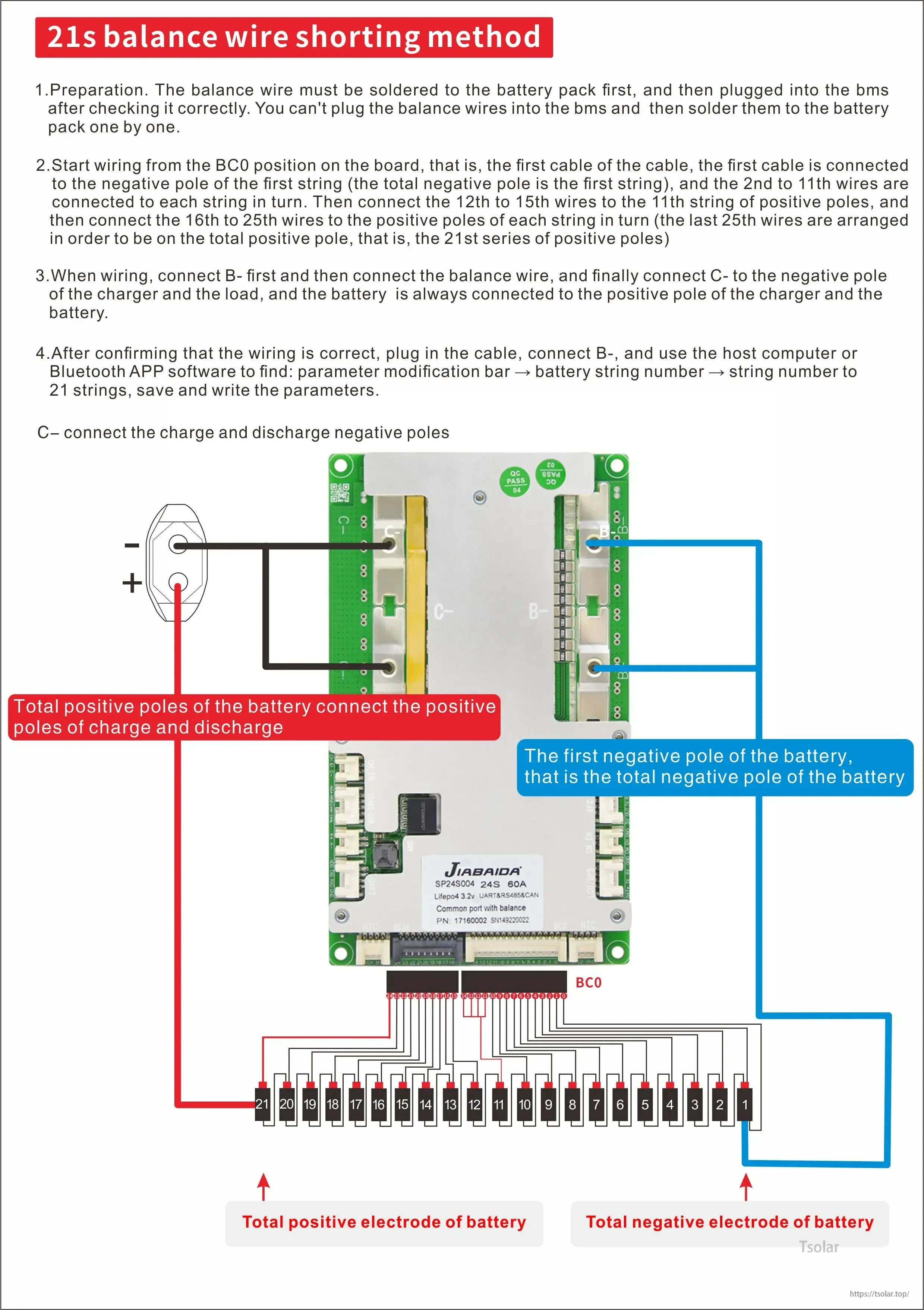
The JBD SP24S004 Smart BMS wiring diagram maps the 21S balance lead sequence and the correct P+ and C- battery connections for setup.
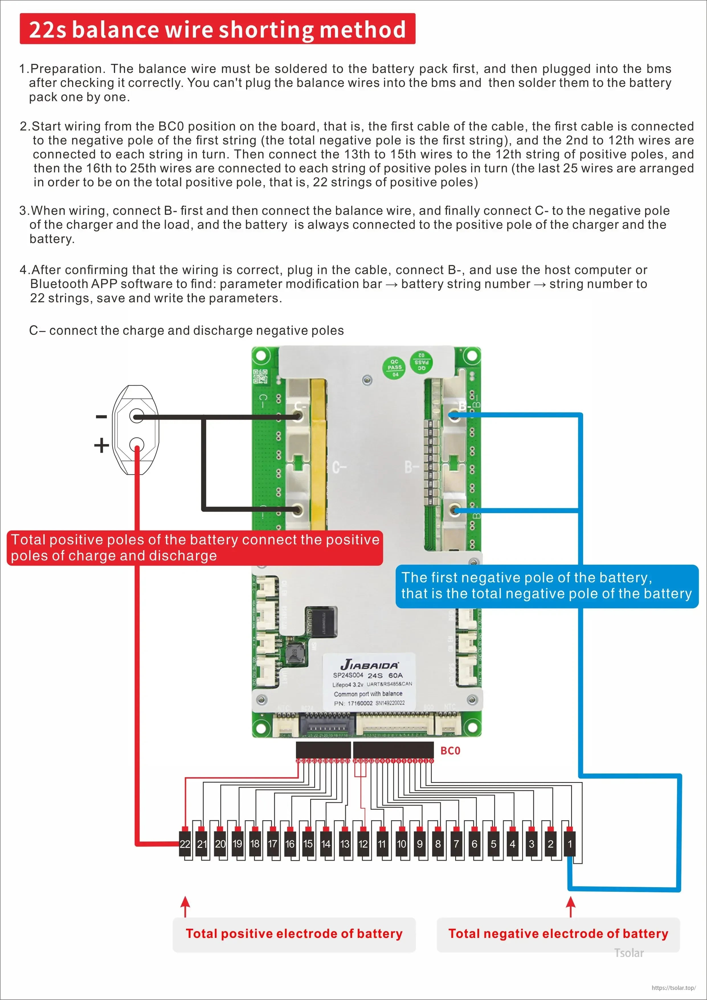
JBD Smart BMS connections are laid out with numbered 22S balance leads plus clear charge/discharge and battery positive/negative wiring points.
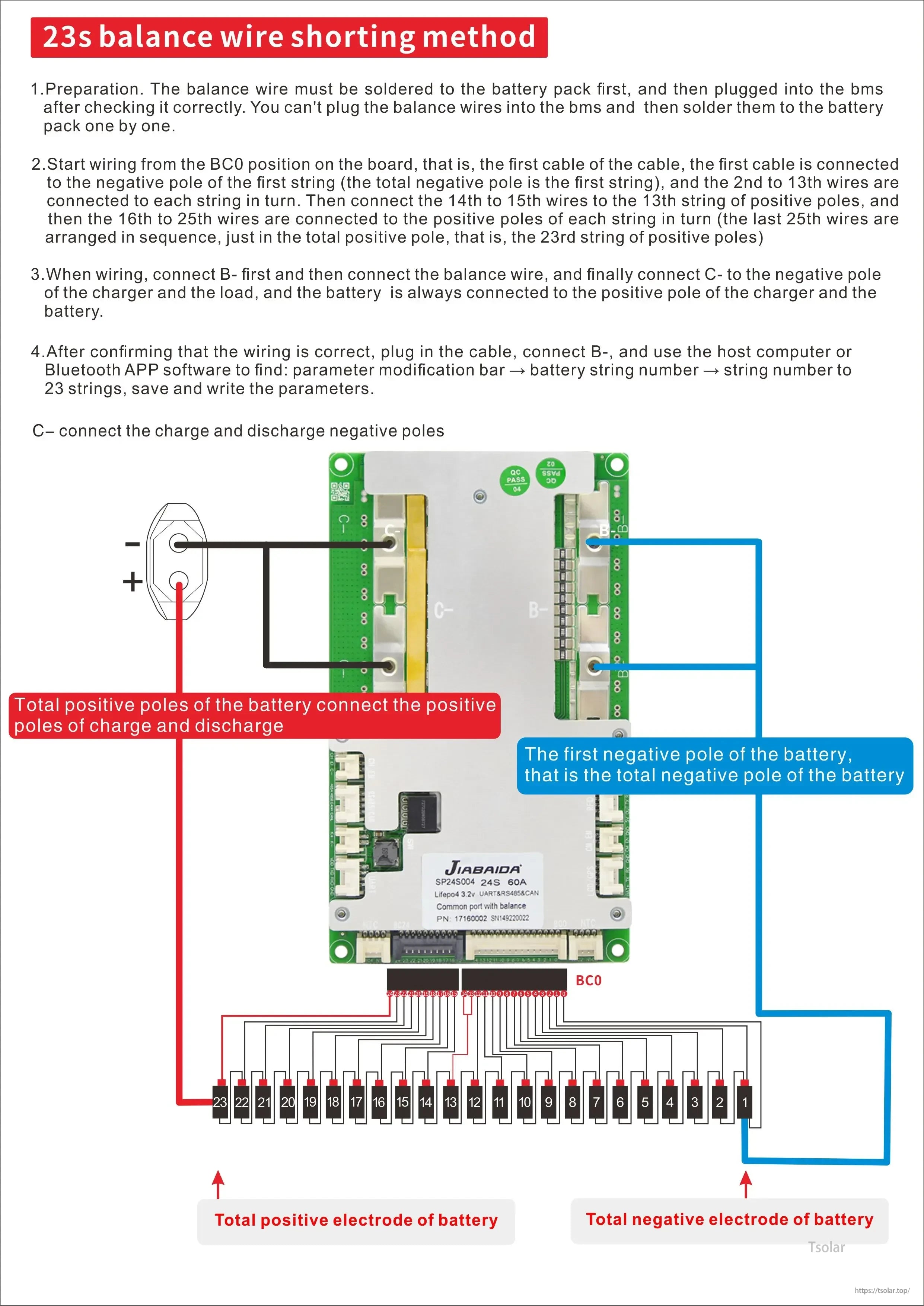
JBD SP24S004 Smart BMS wiring uses a 23S balance lead sequence with separate charge/discharge terminals and clearly marked battery positive and negative connections.
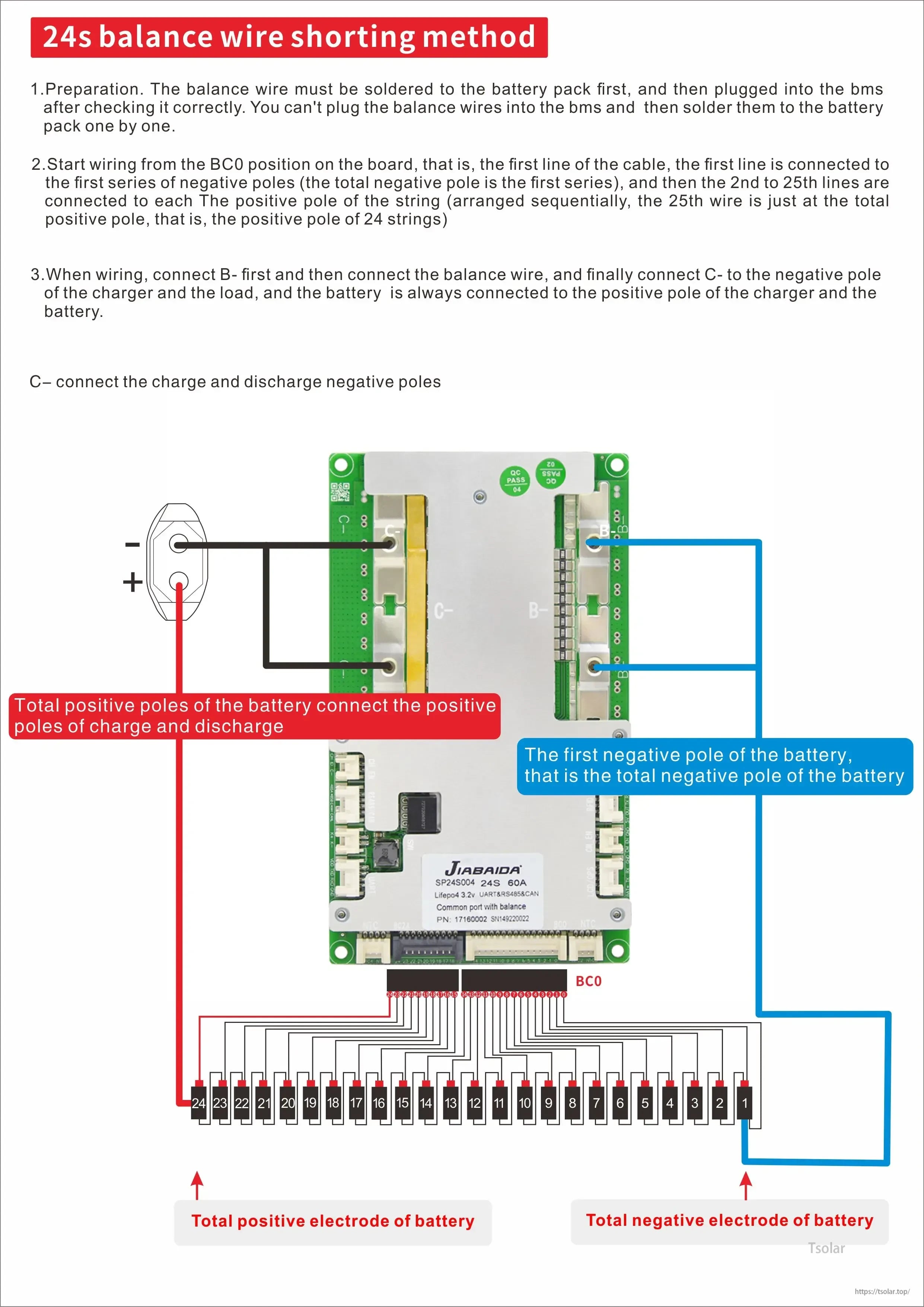
The JBD SP24S004 smart BMS wiring layout maps the 24S balance leads and main B-, charge, and discharge connections to help avoid shorts during installation.

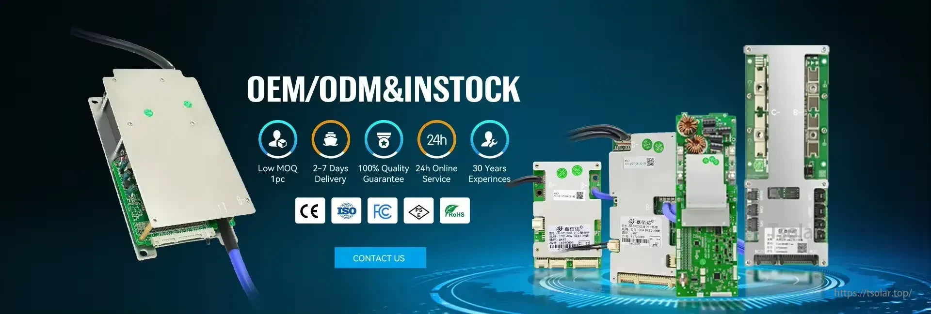
Compliance and quality documentation includes RoHS and ISO 9001 certificates, SGS paperwork, and related test reports.


SMT high-speed mounters and AOI appearance testing support consistent PCB assembly and inspection during production.

JBD SP24S004 smart BMS units go through multiple assembly lines and a full performance test process before delivery.

Multiple payment options are supported, and orders are packed and shipped in cartons on pallets for delivery.