Overview
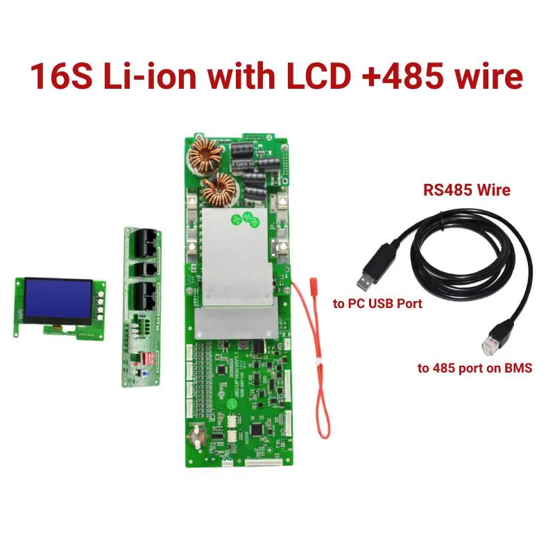
The JBD UP16S010 Battery Management System (BMS) is a smart BMS designed for lithium battery packs used in energy storage and inverter applications. It supports 8S–16S battery strings, a 48V system, and communication via UART/RS485/CAN.
Key Features
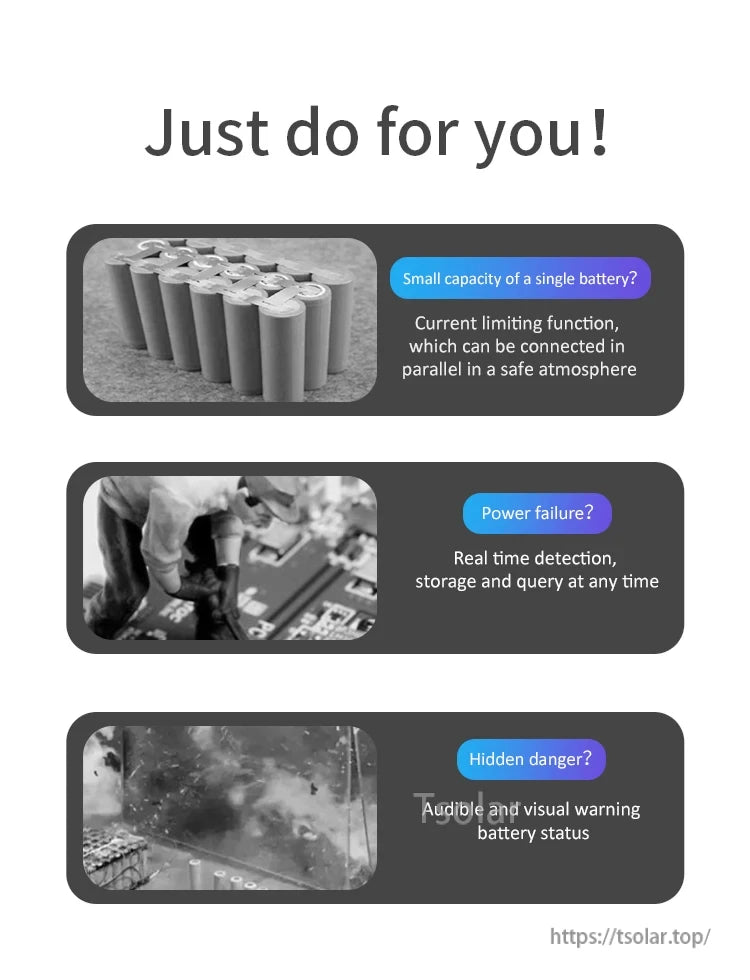
- Supports parallel connection.
- Multiple communication interfaces: UART/RS485/CAN (RS485/CAN parallel interface shown).
- Support display: Yes (Display type: UART/RS485 display). Optional display communication is shown with real-time monitoring menus including: PackInfo, PackStatus, PackPara, PackSet.
- Balance function (common port with balance function).
- Balance current: 20–60 mA.
- Balance way: Static / charge equalization.
- Support automatic identification of string number: Yes.
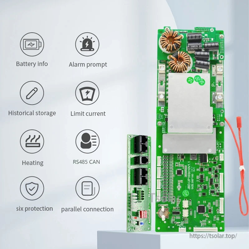
- Good heat dissipation.
- 6 NTCs (as shown/marked in product visuals).
- Pre-discharge function (shown in feature icons).
- Alarm prompt, historical storage, and limit current (shown in feature icons).
- Protection functions shown in feature icons: over charge, over discharge, over current, short circuit, temperature.
- Additional items/labels shown in product visuals: LED working status light, capacity learning ability, buzzer alarm, heating, reserved node, locating hole, open cooling.
- Charging current limiting 20A (shown in product visuals).
- Tin plated terminal (M5) (shown in product visuals).
Specifications
| Product name | Battery Management System |
| Type | Smart BMS |
| Model number | UP16S010 |
| System voltage | 48V |
| Current | 100A–200A |
| Supported strings | 8S–16S |
| Communication | UART / RS485 / CAN |
| Size | 300mm * 100mm * 25mm |
| Support automatic identification of string number | Yes |
| Support display | Yes |
| Display type | UART/RS485 Display |
| Balance current | 20–60mA |
| Balance way | Static / charge equalization |
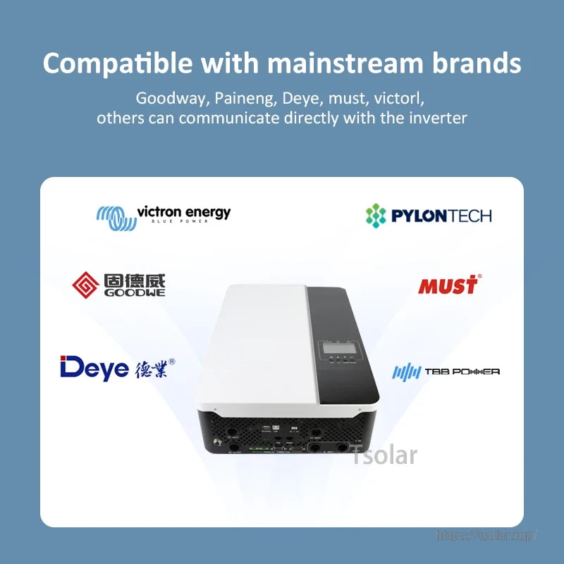
Inverter Communication Compatibility (as listed)
- RS485: Pylon / Growatt_SPF / Voltronic / LXP / Deye / INVT / SRNE / HNJD / SVC / 0LU_VMII
- CANBUS: Pylon / Deye / GoodWe / LXP / Victron / Must / SMA / Growatt / Sofar / GINLONG
Wiring (UP16S010-16S Battery Assembly Wiring Diagram Text)
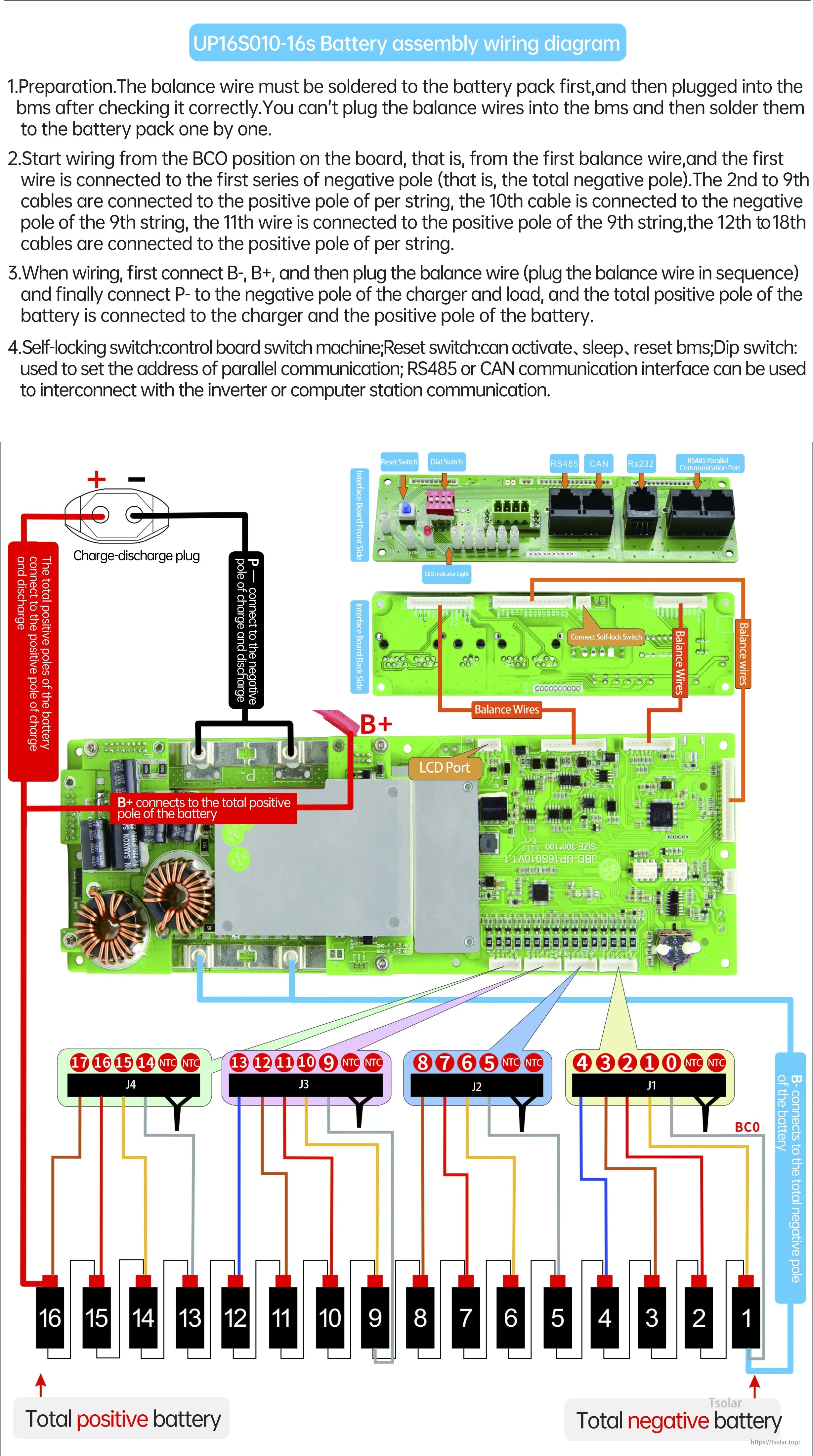
- Preparation: The balance wire must be soldered to the battery pack first, and then plugged into the BMS after checking it correctly. The balance wires cannot be plugged into the BMS and then soldered to the battery pack one by one.
- Start wiring from the BC0 position on the board (from the first balance wire). The first wire is connected to the first series of negative pole (the total negative pole). The 2nd to 9th cables are connected to the positive pole of each string. The 10th cable is connected to the negative pole of the 9th string. The 11th wire is connected to the positive pole of the 9th string. The 12th to 18th cables are connected to the positive pole of each string.
- When wiring, first connect B-, B+, and then plug the balance wire (plug the balance wire in sequence), and finally connect P- to the negative pole of the charger and load. The total positive pole of the battery is connected to the charger and the positive pole of the battery.
- Self-locking switch: control board switch machine; Reset switch: can activate, sleep, reset BMS; Dip switch: used to set the address of parallel communication; RS485 or CAN communication interface can be used to interconnect with the inverter or computer station communication.
Connector mapping shown: J1: 4 3 2 1 0 + NTC + NTC; J2: 8 7 6 5 + NTC + NTC; J3: 13 12 11 10 9 + NTC + NTC; J4: 17 16 15 14 + NTC + NTC.
Software / Tools
- JBD PC Tool Software (download): https://jbdtools.oss-cn-beijing.aliyuncs.com/packfile/JBDTools.zip
For the BMS specification file or wiring for other string counts, contact customer service at service@tsolar.top or visit https://tsolar.top/.
Applications
- Family energy storage (ESS)
- Inverter battery packs
- Electric products
- Other application examples shown: Energy Storage UPS, Recreational Vehicle, Solar Street Light, Electrical Tools, AGV logistics vehicle, electric bicycle/tricycle/car
Details
Smart BMS hardware for 8S–16S lithium battery packs used in energy storage and inverter systems.
Follow the correct balance-lead order and main B+/B− connections to avoid damage during installation.
Multiple communication options support inverter integration and PC monitoring via RS485/CAN.
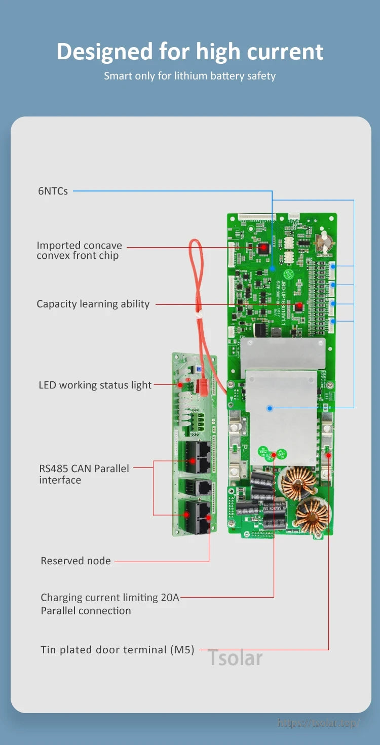
Key on-board details include 6 NTC temperature inputs, LED working status, and tin-plated M5 terminals.
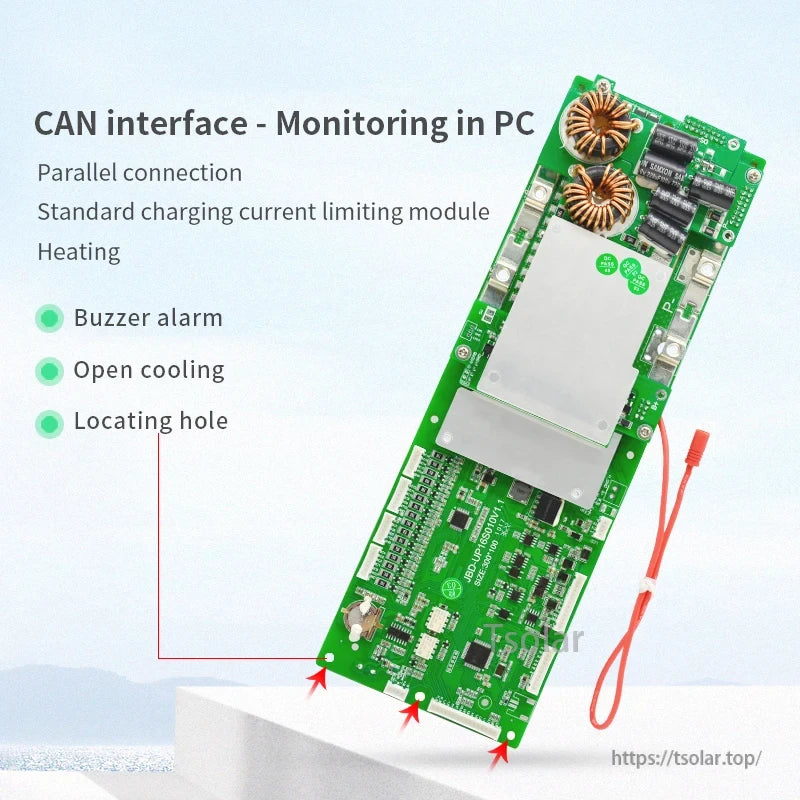
Built-in buzzer alarms and board airflow/clearance features help with fault indication and thermal management.


An optional display provides real-time pack monitoring and quick access to key parameters and settings.
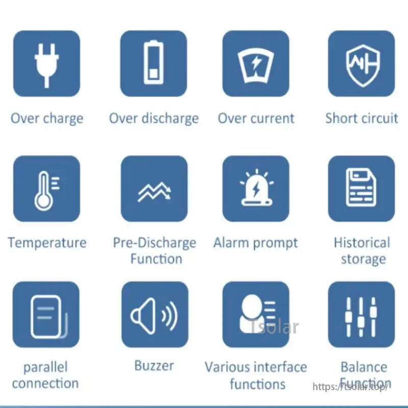
Protection functions cover charge/discharge limits, short-circuit response, temperature monitoring, and pre-discharge.
Designed to communicate with many mainstream inverter protocols through RS485 or CANbus.

Compliance documents and test reports can be provided to support sourcing and project documentation needs.