Overview
The PowMr POW-M25-PRO / POW-M35-PRO / POW-M45-PRO is an MPPT solar charge controller designed for 12V/24V systems with automatic battery voltage detection. It supports multiple battery types and provides multi-stage charging plus load control for off-grid solar and solar energy storage systems.
Key Features
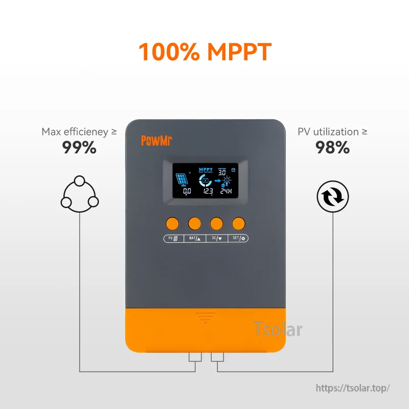
MPPT charging and efficiency
- Charging technology: MPPT
- Charging algorithm: 3 stages (Bulk / Absorption / Float)
- Max. Power Point Tracking Efficiency: >99%
- Conversion Efficiency: ≤98%
- PV utilization: ≥98%
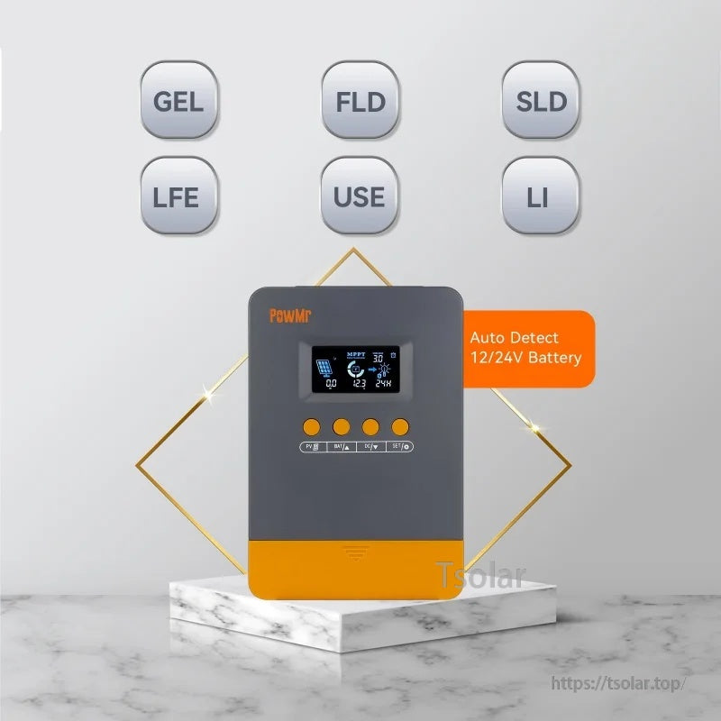
Multiple battery types (12V/24V)
- Auto Detect 12/24V Battery
- Compatible battery type labels shown: AGM, GEL, FLD, LI, SLA
- Battery type selections shown (sequence / display / battery type):
- 1 / SEL / Sealed lead-acid battery
- 2 / GEL / Gel sealed lead-acid battery
- 3 / FLD / Flooded lead-acid battery
- 4 / LO4 / 4S lithium iron phosphate battery
- 5 / LO7 / 7S lithium iron phosphate battery
- 6 / LO8 / 8S lithium iron phosphate battery
- 7 / NO3 / 3S lithium-ion battery
- 8 / NO6 / 6S lithium-ion battery
- 9 / NO7 / 7S lithium-ion battery
- 10 / USE / User-defined
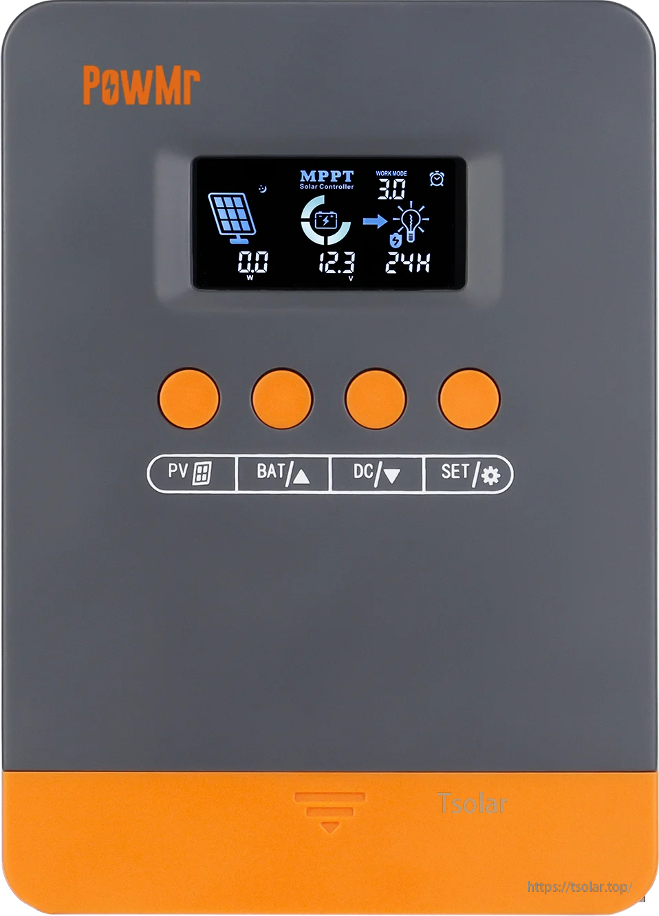
LCD display and button operation
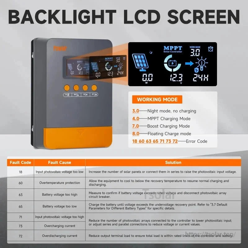
- Backlight LCD screen
- Front panel keys shown: PV, BAT, DC, SET
- Battery type setting note shown: long press BAT key to enter the setting program; use BAT and DC keys to toggle battery type options; press SET key to save and confirm; USE enables user-defined battery parameters.
Load work modes
- 00H: Load Turn OFF
- 24H: Load always Turn ON
- 01H~23H: Time control (Set load ON’s duration)
- Load mode description shown: 0h turns the load on at startup, 24h provides continuous power, and 1–23h allows setting daily on-times.
Protections and fault codes (shown)
- Reverse current
- Reverse polarity protection
- Overload protection
- Short circuiting
- Overcharging
- Over-discharging
- Over temperature protection, over voltage protection
Fault codes table (Fault Code / Fault Cause / Solution):
- 18: Input photovoltaic voltage too low — Increase the number of solar panels or connect them in series to raise the photovoltaic input voltage.
- 60: Overtemperature protection — Allow the equipment to cool to below the recovery temperature to resume normal charging and discharging.
- 63: Battery voltage too high — Measure to confirm if battery voltage exceeds rated voltage and disconnect photovoltaic array circuit breaker.
- 65: Battery voltage too low — Charge the battery until voltage exceeds the undervoltage recovery point.
- 71: Input photovoltaic voltage too high — Reduce the number of photovoltaic arrays connected to the controller to lower photovoltaic input, or adjust series or parallel connections to reduce voltage or current value.
- 73: Overcharge current — Reduce output terminal load to ensure total load is within rated limits of the controller and battery.
- 72: Overdischarge current — Reduce output terminal load to ensure total load is within rated limits of the controller and battery.
Specifications
| Brand Name | PowMr |
| Model Number | POW-M25/M35/M45-PRO (POW-M25-PRO / POW-M35-PRO / POW-M45-PRO) |
| Certification | CE |
| Display | LCD Display |
| Is Smart Device | No |
| Nominal System Voltage | 12V/24V (Auto) |
| Battery Voltage Range | 9~30V |
| Maximum Current | MPPT 25A / 35A / 45A |
| Rated Charging Current | 25A (M25) / 35A (M35) / 45A (M45) |
| Rated DC Output Current | 15A (M25) / 20A (M35) / 25A (M45) |
| Max. Solar Array Open-Circuit Voltage | 100VDC |
| Input Voltage Range | For 12V system: <60V (M25) / <80V (M35) / <100V (M45); For 24V system: <60V (M25) / <80V (M35) / <100V (M45) |
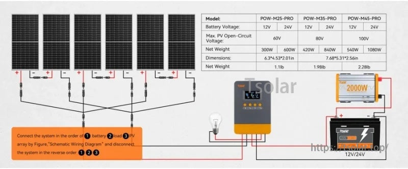
| Max. Input Power (12V) | 300W (M25) / 420W (M35) / 540W (M45) |
| Max. Input Power (24V) | 600W (M25) / 840W (M35) / 1080W (M45) |
| Charging Algorithm | 3 stages |
| Conversion Efficiency | ≤98% |
| Max. Power Point Tracking Efficiency | >99% |
| MPPT Efficiency | 97% to 99% |
| Temperature Compensation | -3mV/°C/2V (default) |
| Self-Consumption | 44mA/12V; 26mA/24V |
| IP Class | IP32 |
| Operating Temperature Range | -35°C~+45°C |
| Humidity Range | ≤95% Non-condensing |
| Altitude | <3000m |
| Dimensions | 160x115x51mm (M25); 195x135x65mm (M35); 195x135x65mm (M45) |
| Net Weight | 500g (M25); 900g (M35); 1035g (M45) |
| High-concerned chemical | None |
| Origin | Mainland China |
| is_customized | Yes |
| Application | Charger Controller, Voltage Controller, Lighting Controller, Solar System Controller, Solar Working Station |
Wiring / Setup Notes (shown)
- Connection order note shown: Connect the system in the order of (1) battery (2) load (3) PV array; disconnect the system in the reverse order (1)(2)(3).
- 2 Step Easy Connection (shown):
- 1) Wiring the battery (*breaker is open)
- 2) Wiring solar panels (*breaker is open)
- 3) Connect battery: controller power on (*battery breaker close)
- 4) Connect solar panels: charging (*both PV battery breaker close)
Applications
- Off-grid solar systems
- Solar energy storage systems (12V/24V)
- Solar lighting control and DC load control
For product selection support (25A/35A/45A) and setup assistance, contact customer service at service@tsolar.top or visit https://tsolar.top/.
Details
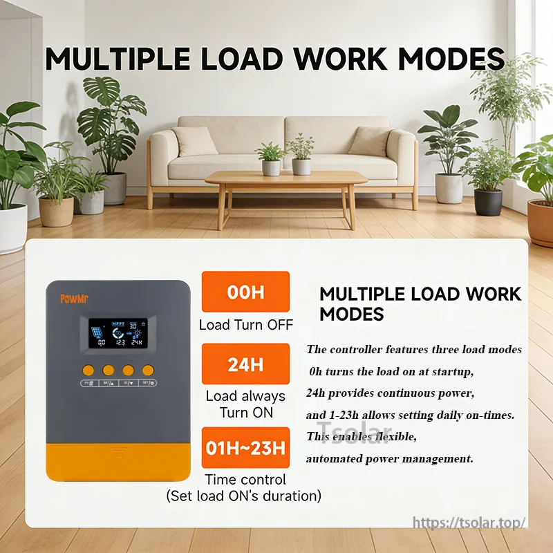
Choose between load off, always-on output, or a daily timer (1–23 hours) for flexible DC load control.

Automatic 12V/24V detection and broad battery support make it easy to match common lead-acid and lithium setups.

Follow the illustrated wiring order to connect battery, load, and solar panels for a clean off-grid installation.
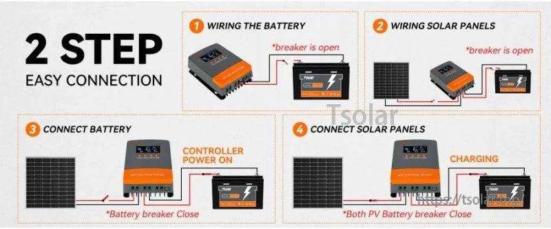
Connect the battery first to power up the controller, then connect the PV input to begin charging.


Multi-stage charging progresses through bulk, absorption, and float to support healthy battery charging behavior.
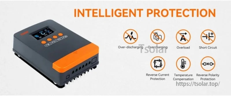
Built-in protections help guard the system against common wiring mistakes and electrical faults.